Thermal Stability Optimization of the Luojia 1-01 Nighttime Light Remote-Sensing Camera’s Principal Distance
by
 , ,
, ,
Kun Zhang
1,2,3, 
Xing Zhong
1,2,3,* ,
,
Guo Zhang
4,
Deren Li
5,
Zhiqiang Su
3,
Yao Meng
3 and
Yonghua Jiang
4 1
Changchun Institute of Optics, Fine Mechanics and Physics, Chinese Academy of Sciences, Changchun 130033, China
2
University of Chinese Academy of Sciences, Beijing 100049, China
3
Chang Guang Satellite Technology Co. LTD, Changchun 130102, China
4
School of Remote Sensing and Information Engineering, Wuhan University, Wuhan 430079, China
5
State Key Laboratory of Information Engineering in Surveying, Mapping and Remote Sensing, Wuhan University, Wuhan 430079, China
*
Author to whom correspondence should be addressed.
Sensors 2019, 19(5), 990; https://doi.org/10.3390/s19050990
Submission received: 21 December 2018
/
Revised: 18 February 2019
/
Accepted: 21 February 2019
/
Published: 26 February 2019
(This article belongs to the Special Issue The Design, Data Processing and Applications of Luojia 1-01 Satellite)
Abstract
:The instability of the principal distance of the nighttime light remote-sensing camera of the Luojia 1-01 satellite directly affects the geometric accuracy of images, consequently affecting the results of analysis of nighttime light remote-sensing data. Based on the theory of optical passive athermal design, a mathematical model of optical-passive athermal design for principal distance stabilization is established. Positive and negative lenses of different materials and the mechanical structures of different materials are matched to optimize the optical system. According to the index requirements of the Luojia 1-01 camera, an image-telecentric optical system was designed under the guidance of the established mathematical model. In the temperature range of −20 °C to +60 °C, the principal distance of the system changes from −0.01 μm to +0.28 μm. After on-orbit testing, the geometric accuracy of the designed nighttime light remote-sensing camera is better than 0.20 pixels and less than index requirement of 0.3 pixels, which indicating that the principal distance maintains good stability on-orbit and meets the application requirements of nighttime light remote sensing.
1. Introduction
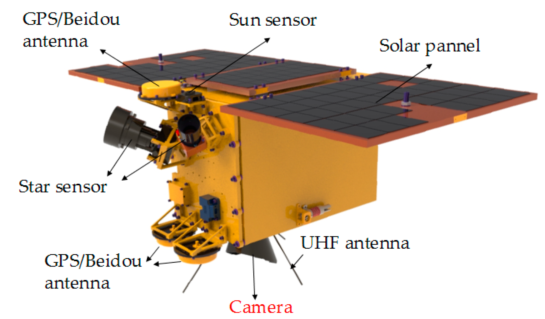
Nighttime light remote sensing generally refers to the process of acquiring visible-light sources such as land and water by remote sensors under cloudless conditions at night [1]. The main payload of the Luojia 1-01 satellite, successfully launched by Wuhan University is, as shown in Figure 1, a remote-sensing camera with nighttime light imaging ability [2,3]. It obtains the ground nighttime light through the camera system, and uses them for corresponding analysis [4,5,6]. The applications of nighttime light remote sensing mainly include: military target detection, urbanization-process analysis, light-pollution analysis, marine-fishery monitoring, battlefield-situation assessment, and natural-disaster monitoring [7,8].
The image registration of the Luojia 1-01 nighttime light remote-sensing camera needs to be performed at different times. The image-registration accuracy directly affects the accuracy of the analysis results [3,4,5,6]. Since nighttime light is a point target and sparsely distributed, it is difficult to improve the registration accuracy through geometric calibration using the natural objects of extended targets, as is done with daytime-imaging remote sensors [9]. Therefore, the stability of the optical system’s principal distance is very important; otherwise, the instability of the principal distance will affect the accurate positioning of the light in the image coordinates [10,11,12]. However, the working environment of the nighttime light remote-sensing camera is extremely harsh, and temperature change is very significant, causing changes to the principal distance of the camera. Due to the limited resources of micro/nano satellites, it is difficult to achieve precise temperature control. Compared with large satellites, the camera will withstand larger temperature fluctuations. Therefore, it is necessary to research the thermal stability of the principal distance [10]. Previously, many researchers have studied the thermal stability of space cameras, but they have all used electronic-active, mechanical-passive, or optical-passive athermal design to optimize the imaging quality, rather than using principal distance as a measurement index [13,14,15,16,17,18].
Aiming at stabilizing the principal distance and imaging quality of the nighttime light remote-sensing camera, an optical-passive-athermal-design mathematical model with a stable principal distance was established. Under the guidance of the established mathematical model, an optical system with stable principal distance was designed by selecting positive and negative lenses of different materials and the mechanical structure of different materials to optimize the optical system. After on-orbit testing, the geometric accuracy of the Luojia 1-01 camera is better than 0.20 pixels, and the optical system had higher resolution and excellent imaging quality, meeting the expected design requirements.
2. Materials and Methods
2.1. The Relationship Between Principal Distance and Image Point
When the structural parameters of an optical system vary with temperature, the internal-orientation elements of the system will be changed [19,20,21]. These elements mainly include the principal point, principal distance, and distortion. The principal point and distortion can be obtained by ground calibration, to which the position offset of the imaging point can be neglected when the temperature changes. However, the stability of the optical system’s principal distance is the most important factor affecting imaging-point-position offset of the nighttime light remote-sensing camera. Therefore, it is very important to analyze the influence of changes in the principal distance of the optical system upon the position offset of the imaging point.
The relationship between the position offset of the imaging point and the variation of the principal distance of the optical system is given by Equation (1):
here, is the position-offset error of the imaging point, is the variation of the principal distance, is the principal distance of the optical system, is the field of view, is the ideal image height, is the actual image height, and is the relative distortion.
According to the imaging geometric relationship of the Luojia 1-01 camera to the ground, the relationship between the camera-positioning error and the principal-distance variation of the optical system is given by Equation (4):
where L is the accuracy of the camera’s ground positioning, and H is the orbital altitude of the satellite.
2.2. Thermal-Stability Research of the Principal Distance
Thermal stability of space optical systems uses an athermalized design method to optimize the imaging quality [22,23,24,25,26]. The ultimate goal of athermal design is to satisfy the condition that when the object’s surface is infinite, the change of the principal distance with temperature equals the change of the lens barrel with temperature, i.e., the normalized change rate of the principal distance is the same as the linear-expansion coefficient of the lens barrel [27,28,29,30,31].
2.2.1. Focal Power and Achromatic Analysis
When the focal length of an optical system is determined, each optical element must satisfy the focal power distribution (Equation (5)):
here, is the total focal power of the optical system, is the focal power of the i-th lens group, and is the incident height of the first paraxial ray on the i-th lens group.
The chromatic aberration of the optical system is one important factor affecting imaging quality. Therefore, the chromatic aberration of the optical system needs to be corrected. This achromatic aberration needs to satisfy Equation (6):
where is the Abbe number of the i-th lens group.
2.2.2. Temperature-focal-shift Analysis
For n thin lens groups, the temperature-focal-shift coefficient is , as shown in Equation (7):
where f is the focal length of the lens group at the calibration temperature, is the focal length of the i-th lens, T is the temperature, is the linear-expansion coefficient of the lens, is the thermal-refractive-index coefficient of the lens, is the refractive index of the i-th lens, is the refractive index of the environmental medium.
When the temperature changes by , the resulting temperature focal shift of the thin-lens group is . From Equation (9), it can be seen that, when the optical system and the temperature range are determined, both the focal length f and the temperature change are constant. In order to keep the focal length of the optical system unchanged in a certain temperature range, the temperature-focal-shift coefficient must be zero, i.e., Equation (10) must be satisfied:
2.2.3. Defocus Analysis
Equation (11) is the athermalization equation in athermal design. In order to ensure the stability of the principal distance of the optical system, this distance must be constant with temperature. However, according to athermal Equation (11), if the temperature focal shift is zero, temperature defocus will inevitably occur:
here, Ti is the athermal coefficient of the lens, is the thermal expansion coefficient of the mechanical structure, and L is the length of the mechanical structure.
In order to ensure that the defocusing produced by the temperature does not affect the imaging quality of the optical system, the defocusing amount should be less than the focal depth. To increase the number of freedom degrees of the athermal design and to reduce the design difficulty, the mechanical structure between the optical elements in the system is matched by different materials. Therefore, the defocus of the athermal design of the optical system needs to satisfy Equation (12):
where is the thermal-expansion coefficient of the i-th mechanical structure, Li is the length of the i-th mechanical structure, is the central wavelength, and F is the F number of the optical system.
From the above analysis, it is apparent that if the principal distance of the optical system remains stable while achieving athermal design, Equation (13) must be satisfied:
2.3. Optical System Design of the Luojia 1-01 Satellite
2.3.1. Design Requirements of the Optical System
The focal length of a space camera is determined by the resolution, the orbital height of the satellite, and the size of the pixel. The field of view of the optical system is related to the focal length and the size of the detector. The larger the F number of the optical system, the better the signal-to-noise ratio, however, this will increase the weight and volume of the optical system, and the design difficulty will be greatly increased. Considering all kinds of factors, the design specifications of the Luojia 1-01 nighttime light remote-sensing camera are shown in Table 1.
2.3.2. Optical System Design
Another factor affecting the position accuracy of imaging points is the defocusing of the image plane of the optical system. The position of the imaging points in the non-image-telecentric optical system varies with the defocusing of the image plane, while the principal light emitted from each field of view in image-telecentric optical system is parallel to the optical axis and the imaging-point centroid of each field of view does not change with defocusing of the image plane. Therefore, an image-telecentric structure should be designed for the optical system of the Luojia 1-01.
Aluminum alloy (AA), titanium alloy (TA), and indium steel (IS) can be selected for the mechanical structure of space-remote-sensing camera, and their corresponding properties are shown in Table 2. The higher density of indium steel is not conducive to lightweight design. The linear-expansion coefficient of aluminum alloy is larger, which makes it difficult to achieve athermal design. Therefore, titanium and aluminum alloys are selected as far as possible in the matching process of mechanical-structural material.
According to the design requirements of the Luojia 1-01 optical system, the materials of the lens and mechanical structure are matched under the guidance of the established mathematical model. The Zemax optical-design software is used to optimize the optical system. The final structure of the optical system is shown in Figure 2.
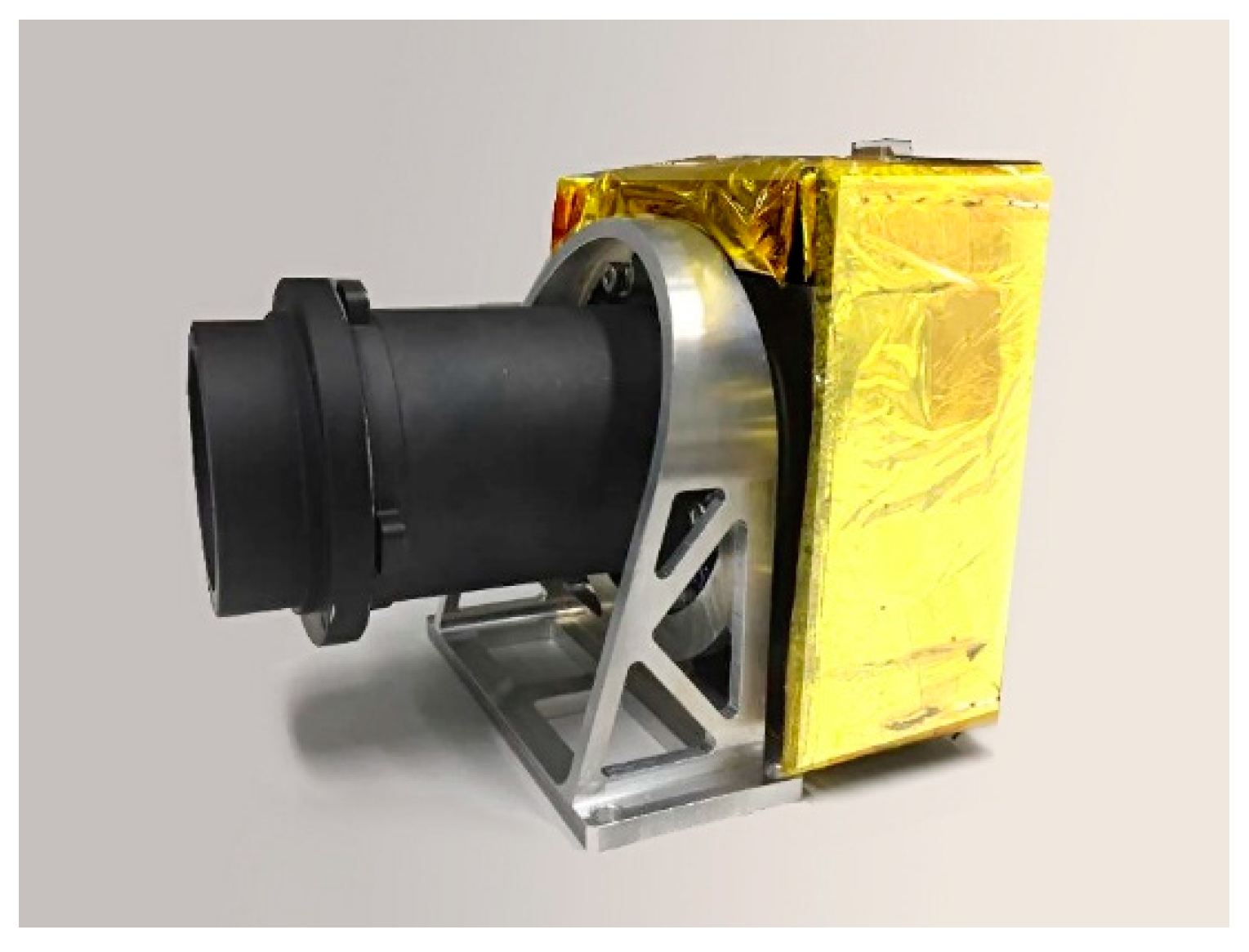
The system is a coaxial-transmission system with compact structure, and the optical elements are easy to process, detect, and assemble. The first piece of the lens uses fused silica to protect the optical system, and the materials of each lens are fused silica, H-ZK6, H-ZK9B, H-F2, H-ZF6, H-ZK9B, H-ZK1, and H-LAK6A. Figure 3 shows the real image of the Luojia 1-01 nighttime light remote-sensing camera.
3. Results and Discussion
3.1. Performance Evaluation of the Optical System
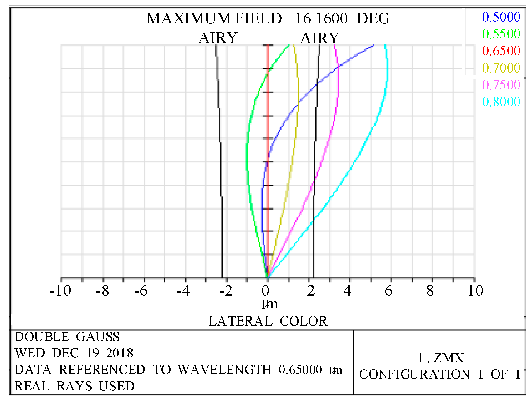
It is important to analyze the imaging performance of the designed nighttime light remote-sensing optical system. The chromatic aberration of this system is one important indicator for measuring the imaging performance. Figure 4 shows the lateral chromatic-aberration curves of the optical system. From Figure 4, it can be seen that the lateral chromatic aberration of the optical system in the full field of view has been well-corrected.
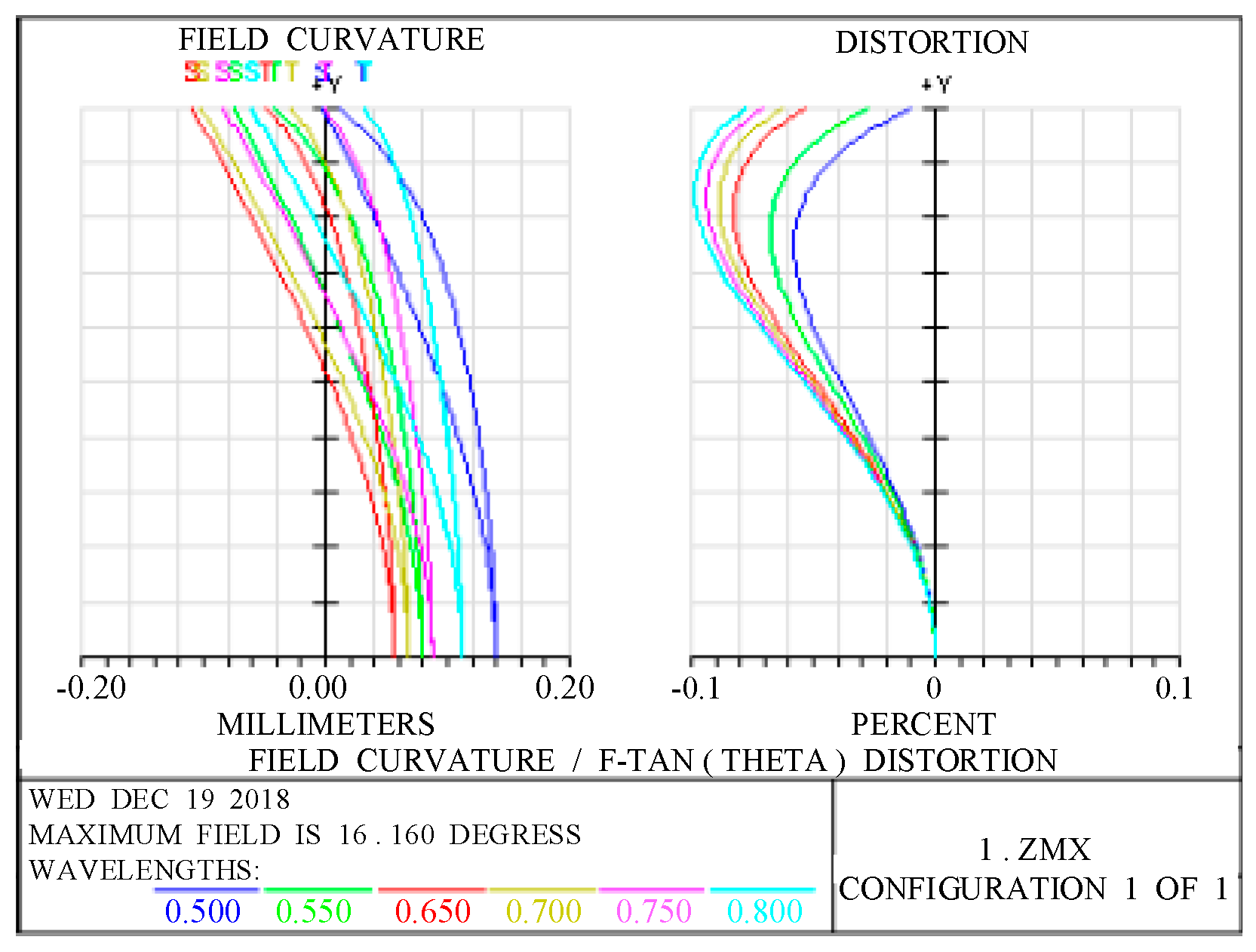
Figure 5 presents the field curve and distortion curves of the optical system. The relative distortion of the full field of view of the optical system is seen to be less than 0.1%, meeting the design requirements.
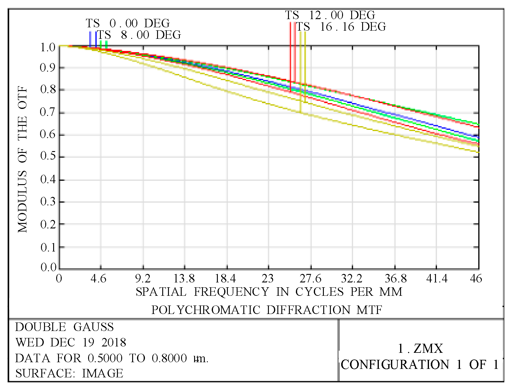
In space-remote-sensing cameras, the modulation transfer function (MTF) is one of the most important indicators for evaluating imaging quality. Figure 6 presents the graph of the MTF of the optical system. Figure 6 shows that at the Nyquist frequency of 46 lp/mm, the MTF of the optical system is better than 0.5 and the imaging quality of the optical system is good.
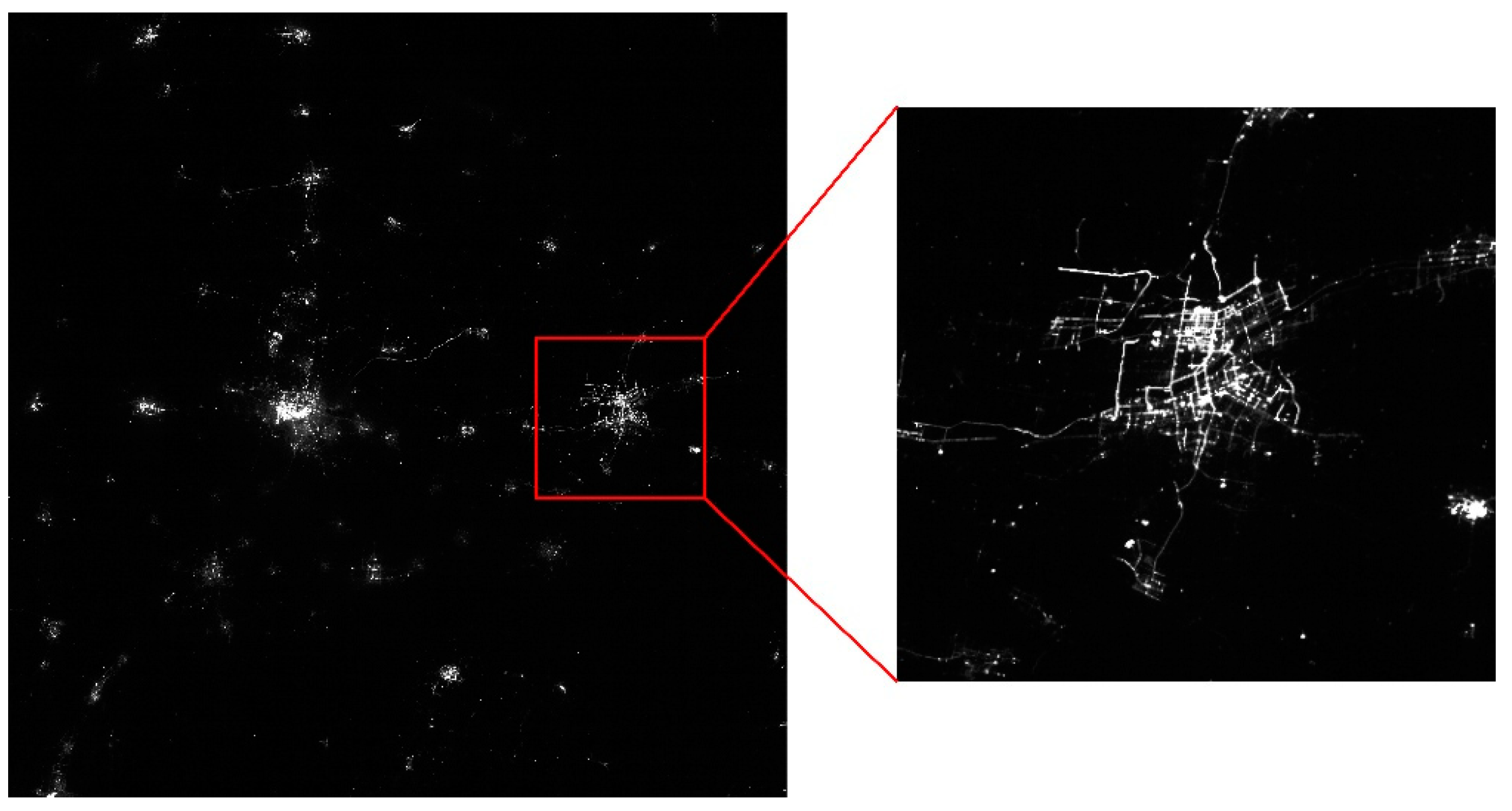
Figure 7 presents an image acquired by the nighttime light remote-sensing camera of the Luojia 1-01.
This camera has high resolution and good imaging quality, and can clearly see roads and blocks, thereby meeting the application requirements of nighttime light remote sensing.
3.2. Thermal Analysis of the Optical System
The results of a reasonable matching of the mechanical-structural materials of the optical system are shown in Table 3.
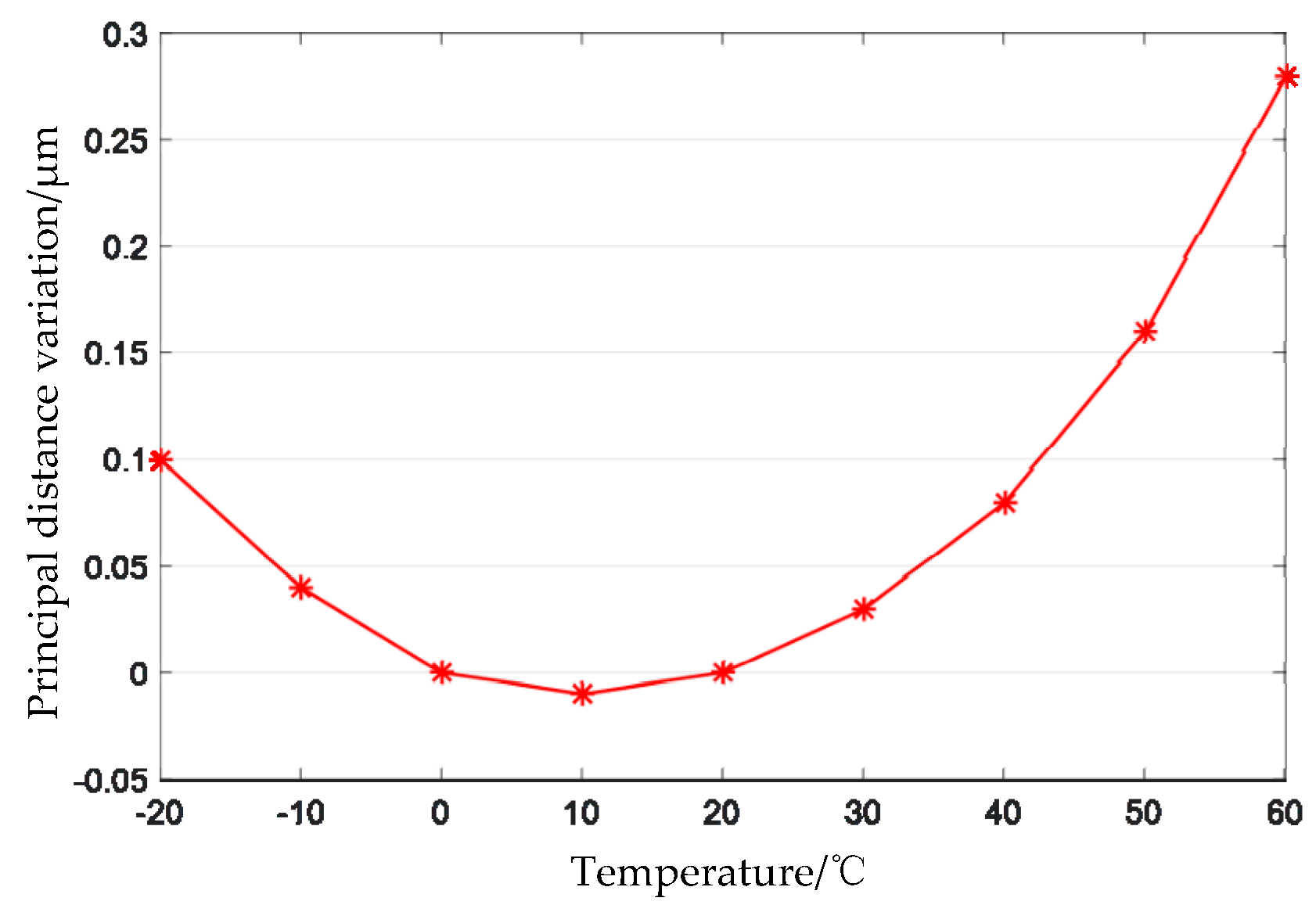
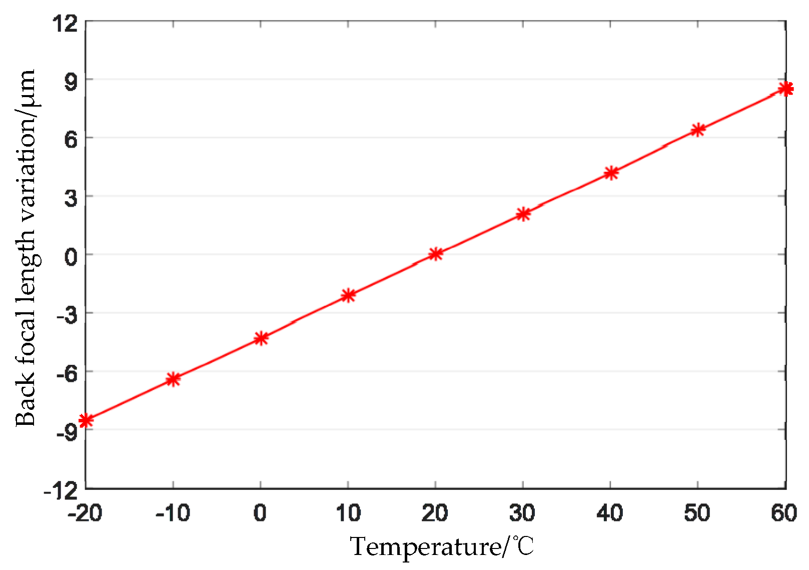
Thermal analysis of the designed optical system is performed. In the range of −20 °C to +60 °C, the relationship between the principal distance of the optical system and the temperature as shown in Figure 8, and the relationship between the back focal length of the optical system and the temperature as shown in Figure 9. From Figure 8, it can be seen that, in the range of −20 °C to +60 °C, the principal distance of the optimized optical system varies from −0.01 μm to +0.28 μm, that is, the maximum change is 0.29 μm, and the corresponding geometric accuracy is 0.008 pixels; Figure 9 shows that the change range of the back focal length of the optical system is −8.5 μm to +8.5 μm, which is less than the half-focal depth of 9.8 μm.
The thermal stability of the MTF of the optical system is analyzed. Figure 10 presents the MTF curves of the optical system. When the temperature is −20 °C, 20 °C, or 60 °C the MTF of the full field of view remains stable and both are better than 0.5, which indicates that the imaging quality of the optical system is stable.
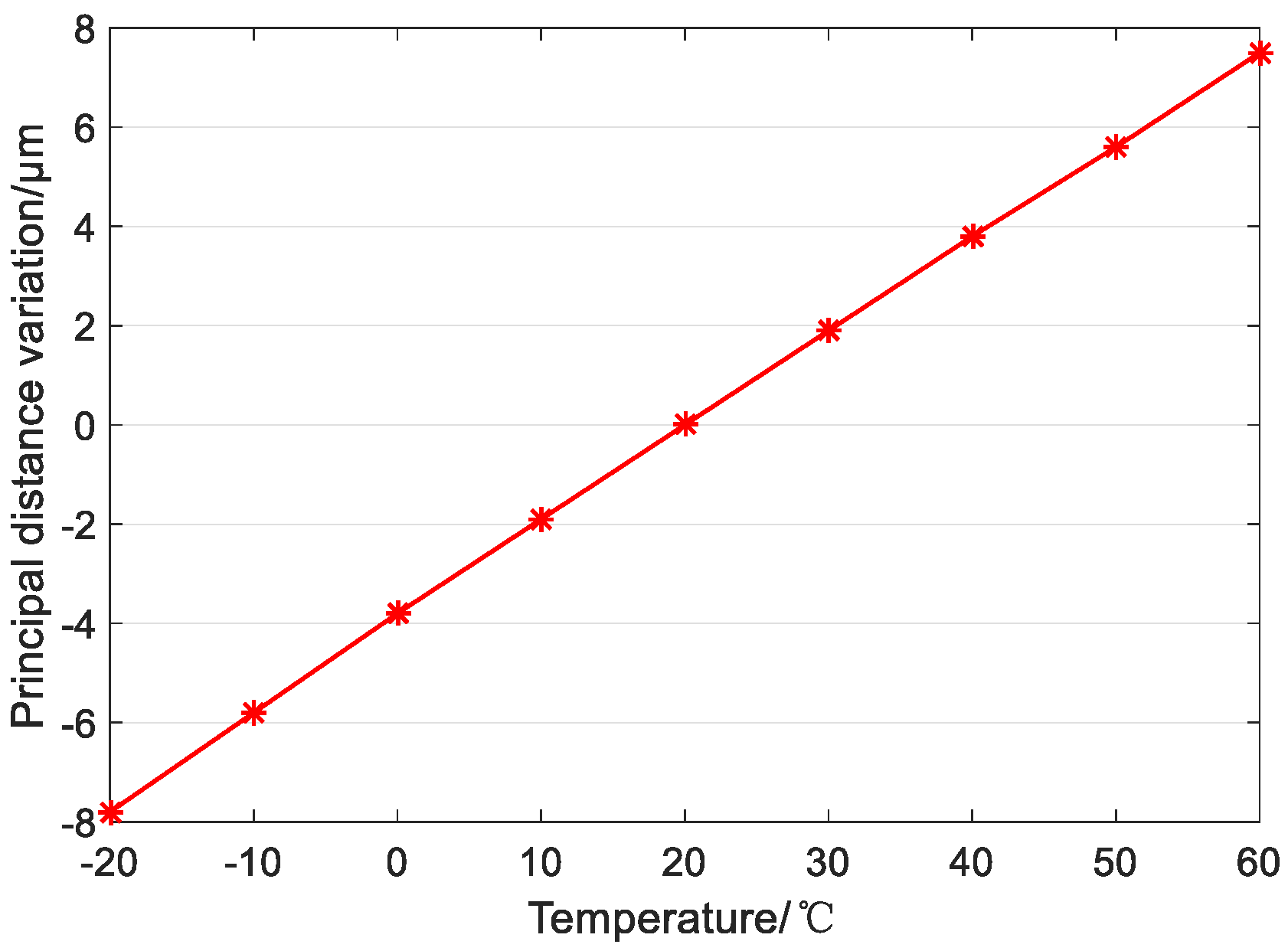
If the optical system is designed by the optical-passive athermal design method, when the optical system achieves athermal design, the materials of each lens are fused silica, H-ZK9B, H-ZK9B, H-F2, H-ZF6, H-ZK9B, H-ZK9B, H-ZK9B, and H-ZBAF52. The material of the mechanical structure adopts titanium alloy. The variation of the principal distance with temperature is shown in Figure 11.
Figure 11 shows that in the temperature range of −20 °C to +60 °C, the principal distance of the optical system changes from −7.8 μm to +7.5 μm, that is, the maximum variation of the principal distance is 15.3 μm, and the corresponding geometric accuracy is 0.40 pixels, which is much greater than 0.008 pixels. From the above analysis, it can be seen that the optimization method proposed in this paper is very effective for the control of the principal distance.
3.3. Distortion Analysis
The principal distance is the most important factor affecting geometric accuracy. After calibrating other intrinsic parameters of optical system remain almost unchanged, in the temperature range of −20 °C to +60 °C, and their impact on geometric accuracy can be neglected, so other intrinsic parameters can’t be considered.
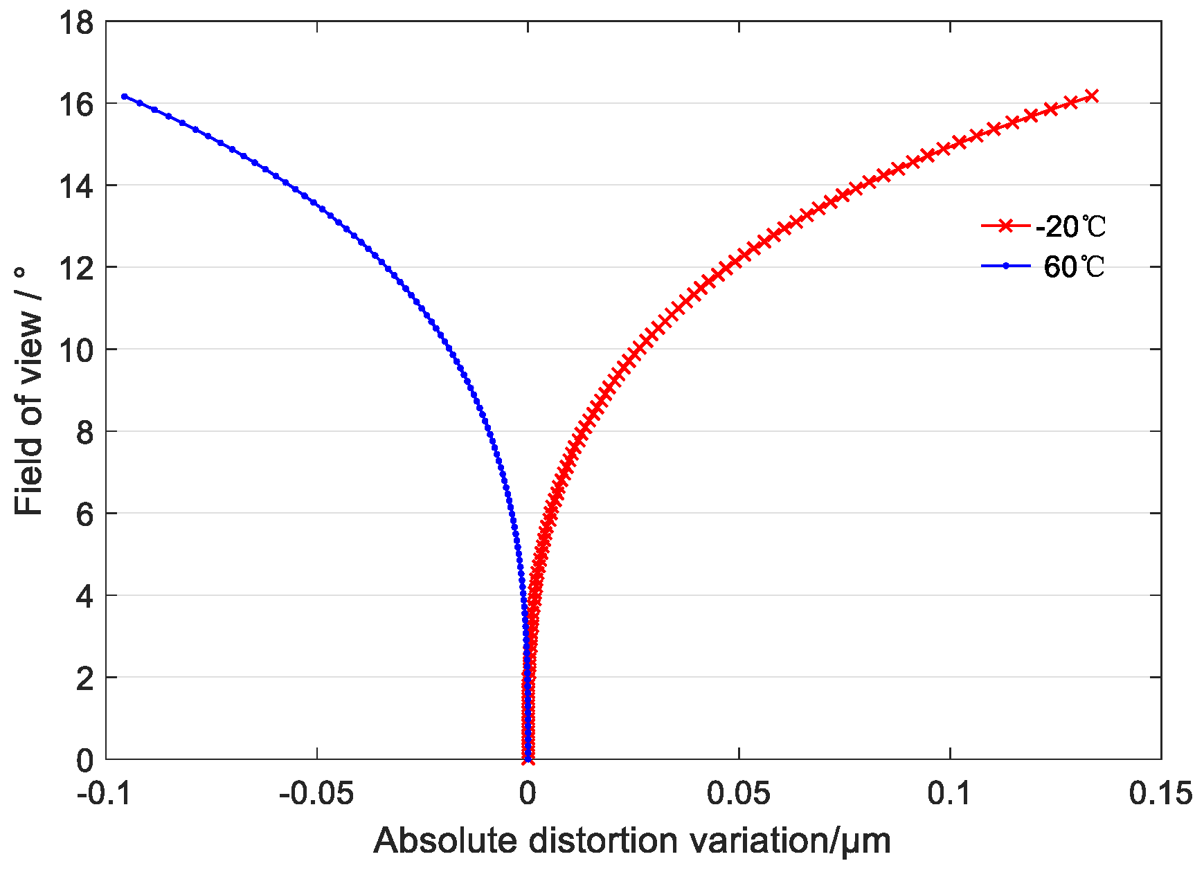
The two curves in Figure 12 shows the law of the absolute distortion variation of the optical system in the full field of view at −20 °C and +60 °C, respectively, compared with the absolute distortion at 20 °C (reference wavelength 650 nm). Figure 12 shows that the maximum distortion of the full field of view of the optical system is less than 0.14 μm and the corresponding geometric accuracy is 0.012 pixels in the temperature range of −20 °C to +60 °C. Therefore, the effect of temperature on the principal distance can be ignored.
3.4. On-Orbit Geometric Test Result
The principal distance variation of the Luojia 1-01 camera design is controlled at the sub-micron scale, so the principal distance variation can’t be measured directly and the stability of the principal distance can only be verified by a calibration method. When the temperature of the camera and environment is 20 °C, the principal distance, principal point and distortion of the camera are calibrated. When the temperature of the camera changes, the camera images the control point, and then use the calibration parameters at 20 °C to resolve the geometric accuracy of the Luojia 1-01 camera.
The Luojia 1-01 nighttime light remote-sensing camera adopts roller shutter mode to image. The camera is imaging to the point targets, so its geometric calibration accuracy is very important for image registration. The residual errors after calibration are mainly reflected in the structural stability errors of the satellite, which include the attitude accuracy error and the stability of the camera’s principal distance. Therefore, if the fluctuation of the principal distance occurs on-orbit, the geometric accuracy cannot be guaranteed. Table 4 presents the geometric validation accuracy of the Luojia 1-01 camera in orbit.
In Table 4, Geometric validation accuracy shows that the geometric accuracy of image is better than 0.2 pixels, which indicates that the stability of the satellite’s overall structure is high and the designed Luojia 1-01 camera based on proposed method is well adapted to the temperature fluctuation on-orbit.
4. Conclusions
Available space resources in micro/nano satellites are limited, so it is difficult to achieve precise temperature control. In order to ensure the image-registration accuracy of the Luojia 1-01 nighttime light remote-sensing camera, it is necessary to study the influence of the space thermal environment upon the principal distance of the optical system and to optimize it accordingly. To ensure the stability of the principal distance and imaging quality of the optical system and to improve the environmental adaptability of remote-sensing cameras, a mathematical model of the optical-passive-athermal design with principal distance stability was established. Under the guidance of the established mathematical model, the Luojia 1-01 camera was designed. The advantages of the proposed method over the traditional method are as follows:
- (1)
- When the temperature is in the range of −20 °C to +60 °C, the influence of the principal distance variation on geometric accuracy is increased from 0.40 pixels to 0.008 pixels.
- (2)
- The change of the back focal length is less than the focal depth. The imaging performance of the system is stable, improving the environmental adaptability of the nighttime light remote-sensing camera.
- (3)
- The effect of the variation of the principal distance of the optical system on the distortion can be neglected. That is because the principal distance change of the optimized system has been well controlled.
The principal distance stability research of optical system can expand the use of space cameras and ensure the performance requirements. This technology has broad application prospects. For example, the stability of the principal distance of star sensor is an important factor affecting the attitude measurement accuracy. Therefore, the optical system design method proposed in the paper is very suitable for the design of the star sensor optical system.
Author Contributions
All authors conceived the idea together. K.Z., X.Z., Z.S., and Y.M. designed the Luojia 1-01 camera. G.Z., D.L., Y.J. planned and performed the experiments. K.Z., X.Z. wrote the manuscript and all authors approved the final manuscript.
Funding
This research was funded by the Youth Innovation Promotion Association, Chinese Academy of Sciences Integrated optical microsatellite key technology based on the concept of “intelligent instrument”; the National Science Foundation for Young Scholars of China grant number 61505203.
Acknowledgments
We give thanks to the research team at Wuhan University for freely providing the Luojia 1-01 nighttime light data. The authors thank editors and anonymous reviewers for their valuable comments to improve our manuscript.
Conflicts of Interest
The authors declare no conflict of interest.
References
- Li, X.; Elvidge, C.; Zhou, Y.Y.; Cao, C.Y.; Warner, T. Remote sensing of night-time light. Int. J. Remote Sens. 2017, 38, 5855–5859. [Google Scholar] [CrossRef]
- The Luojia-1A Scientific Experimental Satellite Was Successfully Lunched. Available online: http://www.lmars.whu.edu.cn/index.php/en/researchnews/2169.html (accessed on 2 August 2018).
- Jiang, W.; He, G.J.; Long, T.F.; Guo, H.X.; Yin, R.Y.; Leng, W.C.; Liu, H.C.; Wang, G.Z. Potentiality of using Luojia 1-01 nighttime light imagery to investigate artificial light pollution. Sensors 2018, 18, 2900. [Google Scholar] [CrossRef] [PubMed]
- Zhang, G.; Li, L.T.; Jiang, Y.H.; Shen, X.; Li, D.R. On-orbit relative radiometric calibration of the night-time sensor of the Luojia1-01 satellite. Sensors 2018, 18, 4225. [Google Scholar] [CrossRef] [PubMed]
- Li, X.; Zhao, L.X.; Li, D.R.; Xu, H.M. Mapping urban extent using Luojia 1-01 nighttime light imagery. Sensors 2018, 18, 3665. [Google Scholar] [CrossRef] [PubMed]
- Wang, L.; Chen, R.Z.; Li, D.R.; Zhang, G.; Shen, X.; Yu, B.G.; Wu, C.L.; Xie, S.; Zhang, P.; Li, M.; et al. Initial assessment of the LEO based navigation signal augmentation system from Luojia-1A satellite. Sensors 2018, 18, 3919. [Google Scholar] [CrossRef] [PubMed]
- Superczynski, S.D.; Christopher, S.A. Exploring land use and land cover effects on air quality in central Alabama using GIS and remote sensing. Remote Sens. 2011, 3, 2552–2567. [Google Scholar] [CrossRef]
- Falchi, F.; Cinzano, P.; Duriscoe, D.; Kyba, C.C.M.; Elvidge, C.D.; Baugh, K.; Portnov, B.A.; Rybnikova, N.A.; Furgoni, R. The new world atlas of artificial night sky brightness. Sic. Adv. 2016, 2, e1600377. [Google Scholar] [CrossRef] [PubMed] [Green Version]
- Li, X.; Chen, X.; Zhao, Y.; Xu, J.; Chen, F.; Li, H. Automatic intercalibration of night-time light imagery using robuts regression. Remote Sens. Lett. 2013, 4, 45–54. [Google Scholar] [CrossRef]
- Fan, Q.C.; Liu, H.B.; Su, D.Z.; Tan, J.C. Athermalisation of optical systems and application in star sensor. Infrared Laser Eng. 2009, 38, 226–229. [Google Scholar]
- Liu, H.B.; Tan, J.C.; Hao, Y.C.; Jia, H.; Tan, W.; Yang, J.K. Effect of ambient temperature on star sensor measurement accuracy. Opt. Electron. Eng. 2008, 35, 40–44. [Google Scholar]
- Tan, W.; Luo, J.F.; Hao, Y.C.; Jia, H.; Liu, H.B.; Yang, J.K. Study of effect of temperature change on the image shifting of the optical system in star sensor. Opt. Technol. 2009, 35, 186–189, 193. [Google Scholar]
- Jiang, Y.; Sun, Q.; Liu, Y.; Zhao, L.X. Athermal design for IR optical seeker system with wide FOV. Acta Photonica Sin. 2013, 42, 462–466. [Google Scholar] [CrossRef]
- Zhang, X.; Jia, H.G. Optical design of infrared athermalized objective with large relative aperture. Chin. Opt. 2011, 4, 374–379. [Google Scholar]
- An, X.Q.; Wang, Q.; Song, B. Athermal design of compact uncooled optical system with large relative aperture. Laser Infrared 2015, 45, 795–799. [Google Scholar]
- Zhao, Y.; Deng, J.; Yu, D.Z.; Ma, Y. Design of dual field of view optical system in long wave infrared with optical passive athermalization. Infrared Laser Eng. 2014, 43, 1545–1548. [Google Scholar]
- Zhang, X.H.; Liang, Z.Y.; Chang, Q. Design of an athermalized projection optical system for infrared target simulator. Electron. Opt. Control 2015, 22, 87–89. [Google Scholar] [CrossRef]
- Jiang, L.; Hu, Y.; Dong, K.Y.; An, Y.; Wang, C.; Tong, S.F. Passive athermal design of dual-band infrared optical system. Infrared Laser Eng. 2015, 44, 3353–3357. [Google Scholar]
- Zhang, W.Y. Athermalization design of infrared refractive-diffractive telephoto objective. J. Appl. Opt. 2017, 38, 12–18. [Google Scholar]
- Shi, H.D.; Zhang, X.; Qu, H.M.; Zhang, J.Z.; Jiang, H.L. Design of large relative aperture infrared athermalized optical system with chalcogenide glasses. Acta Optica Sin. 2015, 35, 249–255. [Google Scholar]
- Jiang, B.; Wu, Y.H.; Dai, S.X.; Nie, Q.H.; Mu, R.; Zhang, Q.Y. Design of a compact dual-band athermalized infrared system. Infrared Technol. 2015, 37, 999–1004. [Google Scholar]
- Li, R.Y.; Fu, Y.G.; Liu, Z.Y. Athermalization design of compact medium-wave infrared imaging system. Infrared Technol. 2018, 40, 119–124. [Google Scholar]
- Fu, Y.G.; Huang, Y.H.; Liu, Z.Y. Design of multispectral infrared athermal optical system. J. Appl. Opt. 2014, 35, 510–514. [Google Scholar]
- Zhang, X.; Qiao, Y.F.; Zhu, M.C.; He, F.Y.; Jia, H.G. Two-lens athermalized infrared telephoto objective. Acta Optica Sin. 2014, 34, 250–255. [Google Scholar]
- Gao, D.R.; Fu, Q.; Zhao, Z.; Zhong, L.J. Athermalized telephoto objective design for 8–12 μm infrared wavelength. Infrared Laser Eng. 2014, 43, 3837–3842. [Google Scholar]
- Fu, Y.G.; Huang, Y.H.; Liu, Z.Y. Design of dual-band athermal infrared fisheye optical system. Infrared Laser Eng. 2014, 43, 3329–3333. [Google Scholar]
- Zhang, F.Q.; Fan, X.; Kong, H.; Cheng, Z.D.; Zhu, B. Influence of temperature on infrared optical system and athermal design. Laser Infrared 2015, 45, 854–860. [Google Scholar]
- Tang, T.J.; Wang, X.Y.; Li, Y. Design of athermalizing dual-band compound optical system. Opt. Technol. 2016, 42, 215–219. [Google Scholar]
- Liu, H.O.; Gou, B.L. Athermalized optical system design of space high-definition camera. Electro-optic Technol. Appl. 2015, 30, 10–13. [Google Scholar]
- Tao, Z.; Wang, M.; Xiao, W.J.; Guo, W.K. Design for cooled dual-band infrared refractive-diffractive hybrid optical system of athermalization and wide FOV. Acta Photonica Sin. 2017, 46, 195–203. [Google Scholar]
- Zhang, C.Y.; Shen, W.M. Design of an athermalized MWIR and LWIR dual-band optical system. Infrared Laser Eng. 2012, 41, 1323–1328. [Google Scholar]
Figure 1.
Luojia 1-01 satellite.

Figure 2.
The structure of the optical system.

Figure 3.
Nighttime light remote-sensing camera of Luojia 1-01.

Figure 4.
Lateral color of the optical system.

Figure 5.
Field curve and distortion of the optical system.

Figure 6.
Modulation transfer function of the optical system.

Figure 7.
Nighttime light remote-sensing image.

Figure 8.
Variation of principal distance with temperature.

Figure 9.
Variation of back focal length with temperature.

Figure 10.
Graphs of modulation transfer function. (a) −20 °C; (b) 20 °C; (c) 60 °C.

Figure 11.
Variation of principal distance with temperature.

Figure 12.
Curve of absolute distortion variation with temperature.


Table 1.
Indexes of the Luojia 1-01 camera.
| Focal length/mm | 55 |
| F number | 2.8 |
| Full field of view | 32.32° |
| Spectral range/µm | 0.50–0.80 |
| Primary wavelength/µm | 0.65 |
| MTF (46 lp/mm) | ≥0.50 |
| Temperature range/°C | −20–+60 |
| Image point offset (edge field)/pixels | 0.3 |
Table 2.
Material properties of mechanical structure.
| Material | Aluminum Alloy | Titanium Alloy | Indium Steel |
|---|---|---|---|
| Density/(g/cm3) | 2.70 | 4.51 | 8.10 |
| Thermal expansion coefficient/(10−6/°C) | 23.6 | 9.2 | 1.6 |
Table 3.
Mechanical structure material distribution table.
| Element Spacing Number | 1 | 2 | 3 | 4 | 5 | 6 | 7 | 8 | 9 |
| Material | TA | AA | TA | TA | TA | AA | TA | AA | TA |
Table 4.
Geometric validation accuracy.
| Validation Accuracy | Vertical Direction of the Orbit/Pixel | Orbit Direction/Pixel | Plane Accuracy/Pixel | ||||
|---|---|---|---|---|---|---|---|
| MAX | MIN | RMS | MAX | MIN | RMS | ||
| Geometric Accuracy | 0.30 | 0.00 | 0.13 | 0.46 | 0.00 | 0.15 | 0.20 |
© 2019 by the authors. Licensee MDPI, Basel, Switzerland. This article is an open access article distributed under the terms and conditions of the Creative Commons Attribution (CC BY) license (http://creativecommons.org/licenses/by/4.0/).
Share and Cite
MDPI and ACS Style
Zhang, K.; Zhong, X.; Zhang, G.; Li, D.; Su, Z.; Meng, Y.; Jiang, Y. Thermal Stability Optimization of the Luojia 1-01 Nighttime Light Remote-Sensing Camera’s Principal Distance. Sensors 2019, 19, 990. https://doi.org/10.3390/s19050990
AMA Style
Zhang K, Zhong X, Zhang G, Li D, Su Z, Meng Y, Jiang Y. Thermal Stability Optimization of the Luojia 1-01 Nighttime Light Remote-Sensing Camera’s Principal Distance. Sensors. 2019; 19(5):990. https://doi.org/10.3390/s19050990
Chicago/Turabian StyleZhang, Kun, Xing Zhong, Guo Zhang, Deren Li, Zhiqiang Su, Yao Meng, and Yonghua Jiang. 2019. "Thermal Stability Optimization of the Luojia 1-01 Nighttime Light Remote-Sensing Camera’s Principal Distance" Sensors 19, no. 5: 990. https://doi.org/10.3390/s19050990
Note that from the first issue of 2016, this journal uses article numbers instead of page numbers. See further details here.