Brush-Holder Integrated Load Sensor Prototype for SAG Grinding Mill Motor
by
 , ,
, ,
Miguel Carrasco
1,* ,
,
Francisco Álvarez
2, 
Ramiro Velazquez
3 ,
,
Javier Concha
1 and
Francisco Perez-Cotapos
1 1
Facultad de Ingeniería y Ciencias, Universidad Adolfo Ibañez, Av. Diagonal Las Torres, 20700, Santiago 7941169, Chile
2
Prodin SPA, Condell 679. Providencia, Santiago 7501123, Chile
3
Facultad de Ingeniería, Universidad Panamericana, Josemaría Escrivá de Balaguer 101, Aguascalientes 20290, Mexico
*
Author to whom correspondence should be addressed.
Electronics 2019, 8(11), 1227; https://doi.org/10.3390/electronics8111227
Submission received: 2 October 2019
/
Revised: 24 October 2019
/
Accepted: 25 October 2019
/
Published: 27 October 2019
(This article belongs to the Section Systems & Control Engineering)
Abstract
:One of the most widely used electro-mechanical systems in large-scale mining is the electric motor. This device is employed in practically every phase of production. For this reason, it needs to be inspected regularly to maintain maximum operability, thus avoiding unplanned stoppages. In order to identify potential faults, regular check-ups are performed to measure the internal parameters of the components, especially the brushes and brush-holders. Both components must be properly aligned and calibrated to avoid electric arcs to the internal insulation of the motor. Although there is an increasing effort to improve inspection tasks, most inspection procedures are manual, leading to unnecessary costs in inspection time, errors in data entry, and, in extreme cases, measurement errors. This research presents the design, development, and assessment of an integrated measurement prototype for measuring spring tension and other key parameters in brush-holders used in electric motors. It aims to provide the mining industry with a new, fully automatic inspection system that will facilitate maintenance and checking. Our development research was carried out specifically on the brush system of a SAG grinding mill motor. These machines commonly use SIEMENS motors; however, the instrument can be easily adapted to any motor by simply changing the physical dimensions of the prototype.

1. Introduction
Although electric motors have been used in the mining industry for more than 75 years, it is only in the last 15 years that large-scale mining companies have started to use systems and sensors in their machinery for preventive maintenance, control, and management systems. The motors consist of different parts, some of which, like the carbon brushes, require regular inspection. These conduct the current to the motor blades, generating the magnetic field that causes the motor axle to rotate. Despite their importance, the brushes seldom have integrated monitoring systems that allow their state of wear to be checked, thus enabling maintenance staff to determine when they need replacing. As far as we know, there are no automatic systems for assessing the state of the brush-holders and the springs that maintain pressure on the brushes. These two components are vital for the correct functioning of the motor since undue wear affects not only the brush but also the slip ring, which is a key element of the motor and very expensive to repair. A fault in a slip ring is classified as catastrophic as it implies dismantling the motor, which often costs millions of dollars.
Unplanned stoppages in mine motors due to faults in brush systems occur periodically. Although prediction methods have been developed based on model design and estimated parameters, there is currently no way of accurately predicting the moment when they will fail [1,2,3]. Brush-holder systems are generally referred to as black boxes because the only way of knowing what is happening inside the machine is to stop it completely in order to check its components. To give an idea of the magnitude of the losses, transporter belts move 4500 ton/h of ore at the cost of 0.8 USD/ton, which represents 3600 USD/h. Stoppages on a primary belt can result in costs of approximately USD 500,000 per week. For a large mining operation, the cost of a stoppage due to a fault in a SAG grinding mill is approximately 75,000 USD/h. This is because ore extraction and processing are done in series, meaning that a fault in one machine will affect all subsequent processes. For this reason, the industry has sought to develop plans to meet the need for increased environmental protection, and especially to improve its logistics, concentrating on ensuring greater reliability in the productivity of machinery by improving equipment availability. This is the focus of the present research.
Today, the mining industry has developed various types of sensors to detect mechanical faults, but so far, no sensors exist for determining electrical faults in the motors used in operations, all of which use carbon brushes for electricity transmission. Apart from this, inspection is very complicated in many plants, leading to measurement errors due to the difficulty of positioning the measurement devices correctly. With these circumstances in mind, this research presents an assessment of a prototype brush-holder measurement and inspection device for electric motors that use carbon brushes for electricity transmission.
This research presents a prototype for measuring the force exerted by the brush-holder spring on the brush when it is inserted in its mounting, which simulates the real situation when the motor is functioning. The device works with multiple integrated electronic and mechanical elements, together with a monitoring system that allows the inspector to evaluate in situ whether the variables measured comply with the manufacturer’s control standards or are outside the permitted range. In summary, this research focuses on two main problems related with the brush-holder spring: (1) Brush spring tension measurement; (2) inspector report generation by uploading this information to a mobile application. Our proposed solution is not intended to act while the motor is functioning. Instead, it is meant to assist the inspection process and facilitate the inspector’s work when checking the motor’s parameters. In a high-risk environment like mining, inspection is a critical task since it ensures that machinery and processes function correctly within standardized limits.
1.1. Technical Background
Recently, there has been a considerable increase in the use of sensors to detect mechanical faults in mine equipment, and these have led to an enormous reduction in the number of catastrophic failures in high-stress parts of static machinery. This has been achieved thanks to the miniaturization of electronics. Nowadays, many mine process machines are now fitted with sensors to measure variables such as temperature, vibrations, mechanical stresses, pressure, etc., in order to establish a control panel that will indicate, to some extent, how the machine is working [4,5,6,7].
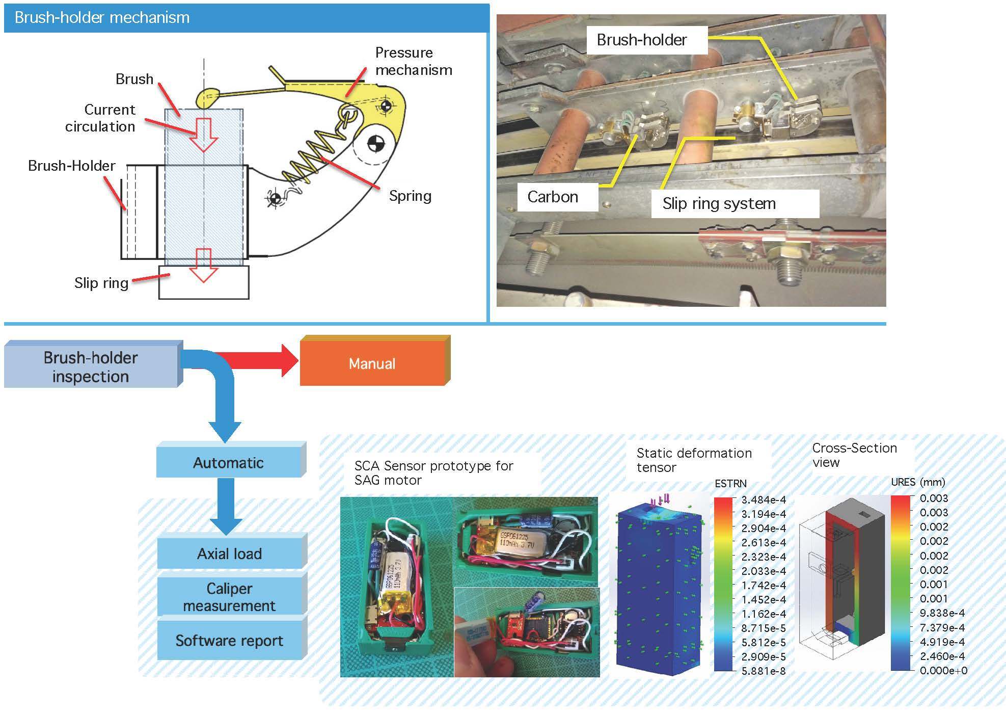
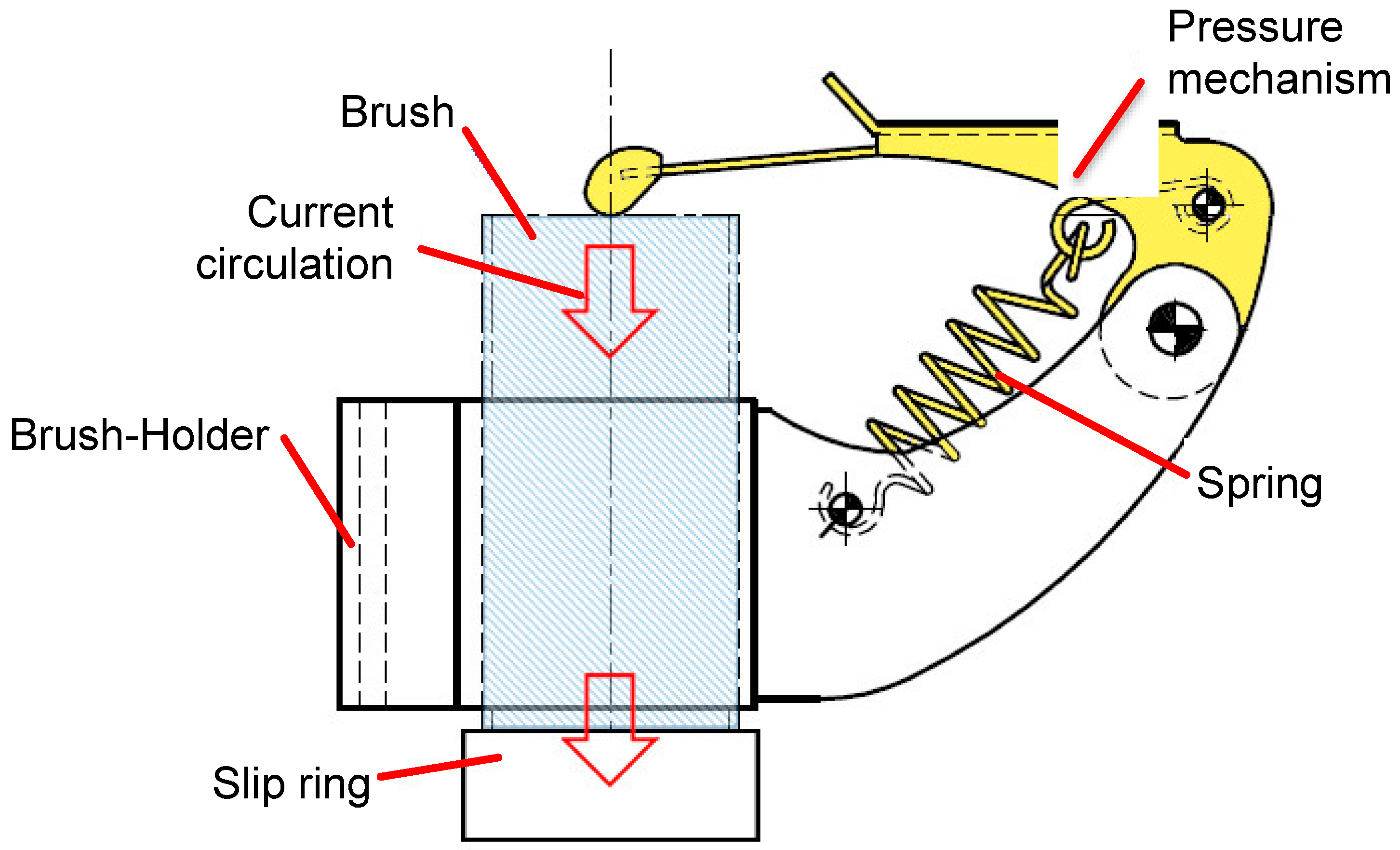
It should be noted that high power electric motors are found in all stages of ore transport and processing, driving the machinery involved. This machinery includes loading shovels, off-road trucks, transporter belts, grinding mills, crushers, etc., which are all electrically powered for reasons of their size and application. The functioning of an electric motor requires the transmission of the electrical current to the internal coils, where the magnetic fields are generated that cause the motor axle to rotate. Carbon brushes are used to transmit the current from the fixed to the rotating parts through a slip ring system (Figure 1a).
Although the brushes are considered to be wear-out elements and are tiny parts of the motor, the absence or malfunctioning of a brush will cause the motor to stop. These faults may occur, for example, due to accelerated wear of the brushes, incorrect contact pressure, or non-uniform distribution of the current, resulting in high temperatures, electric arcs, and damage to the internal insulation of the motor [8,9]. The continued existence of one of these anomalous situations may lead to a catastrophic failure of the motor, and consequently, to substantial economic losses.
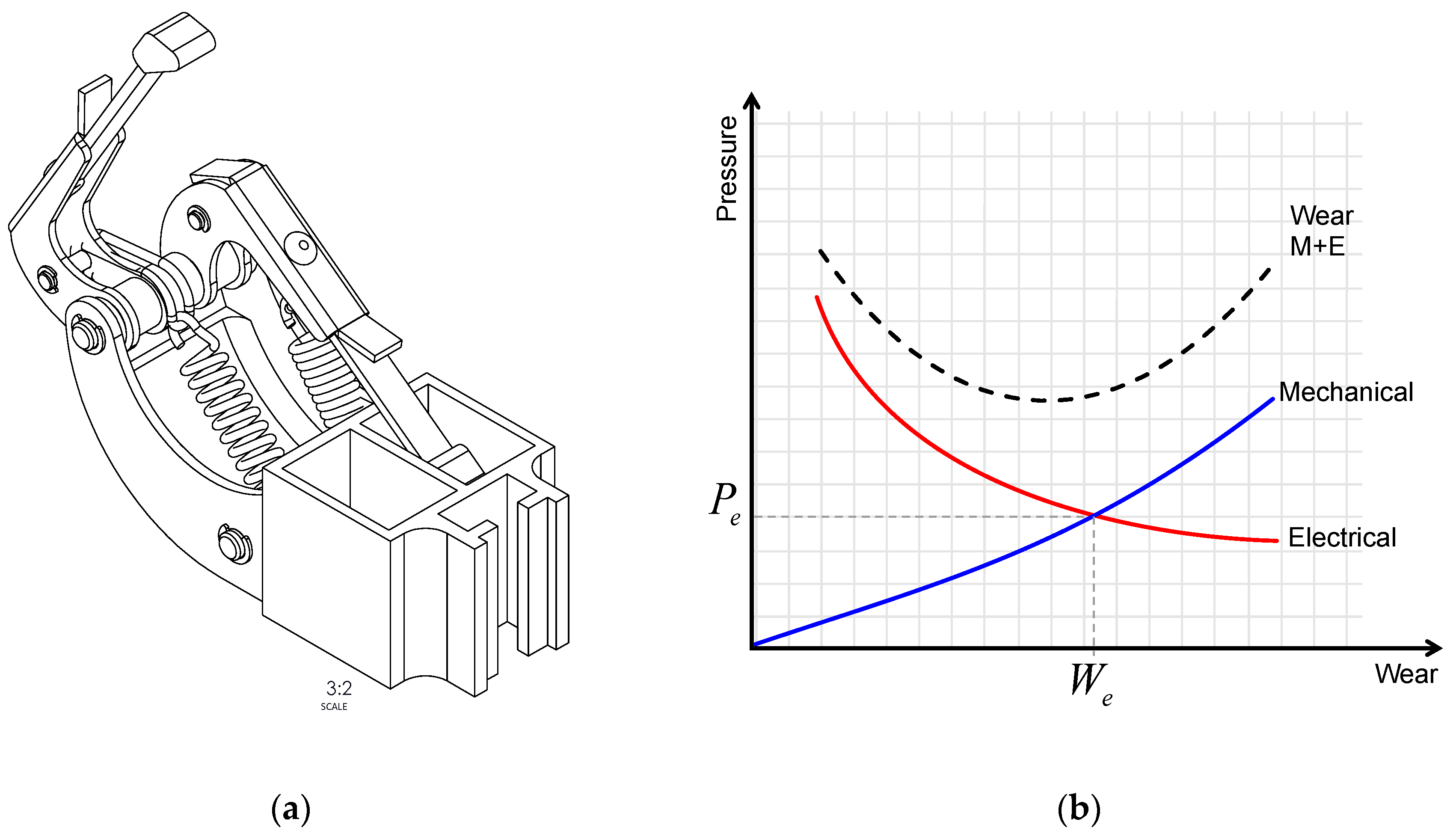
In general, motors can only be inspected when they are stopped. The only way of assessing the state of the brushes and other parts of the motor is by physical inspection carried out in situ by an operator. Normally, inspection requires the use of various measuring instruments. For example, a dynamometer is used to measure the pressure of the brush spring, an internal caliper to take the internal axial measurements of the brush-holder, and an external caliper to measure the length of the brush. Although these measurements are important, the pressure of the brush mounting is fundamental as it is related to the friction of the brush on the slip ring. Too high pressure will accelerate the mechanical wear of the brush, while too low pressure will result in electric arcs, producing a rapid deterioration of the electrical components in the ring, the brush, and even the brush-holder [8]. Correct measurement allows the inspector to check that the parameters of the various pressure mechanisms are within the recommended ranges to produce uniform wear of the carbon brush, and therefore comply with the ranges established for maintenance programs. In general, the maintenance plan aims to find an optimum point at the intersection of the pressure and wear curves for the contact point of the brush (We, Pe) (Figure 1b).
1.2. Existing Inspection Process
The existing inspection process is generally carried out by a team of two or more highly qualified human operators, due to the high risk of death in the event of incorrect operation and/or permanent damage to the plant [9]. The job typically consists of adjusting the brush-holders and measuring the spring tension. In order to do this, the motor must be stopped, blocked, and disconnected from the power source. This requires the inspection staff to block the control panel with padlocks, known as LOTO-blocking [10], to ensure maximum control of the machine and avoid accidents.
Because of the danger for the plant, access to the motor requires strict control by the operators. Only the items necessary for the inspection can be taken into the machine, and an inventory is taken before entry and after exit. Losing anything inside the motor can extend the inspection and maintenance time because nothing must be left inside, especially objects that may affect the internal parts such as coils and rings, which are very difficult to remove. To avoid dropping or losing any equipment, the operator usually keeps all his tools attached to his wrist by a lanyard.
Inspection and/or maintenance are usually divided into three stages: (1) Measuring and changing brushes, (2) regulation of the brush-holder(s), and (3) measuring the working tension of the brush springs. The parameters generally measured are the pressure exerted on the brushes by the spring mechanism, the internal measurements of the brush-holder, and the state of the slip ring. From this information, together with a visual inspection, the inspector produces a report on the state of the motor. If there is any parameter that does not conform to the standards, the part is changed, or the assembly is regulated.
The measurement protocol used today includes paper forms for recording the measurements of each part inspected. Unfortunately, this process is slow, complicated, and subject to errors because it places a high burden on the human operator in terms of information collection and recording, leading to possible errors in measurement, reading, or even data entry into the form. Furthermore, these formal inspection plans generally refer to major maintenance, and it is therefore difficult to design a mechanism for assessing the state of the machine over time. A historical record of the data could help in designing models for fault prevention and traceability control [11,12].
1.3. SAG Grinding Mills
The electric motors used in SAG grinding mills are enormous. They possess multiple contact points since they have to drive very heavy machinery that is around 12 m in diameter and a capacity bigger than 100,000 tpd (ton per day) [13]. To do this, they use a combination of brush-holder pairs, each with independent springs distributed in different chambers around the mill. Each contact point corresponds to a different phase of the motor when current is transmitted from the brushes to the coils, and each must be inspected, photographed, and calibrated if necessary. Due to the large size and physical dimensions of the motor, and the confined spaces in which maintenance is carried out, the time required for inspection is increased by the need for the operator to move about inside the structure in each phase of the process
Although the brushes depend on the configuration of the motor, the industry typically uses brushes configured in pairs. The dimensions of the brushes of the SAG grinding mill used in this research are 50.00 × 25.00 × 16.00 mm. They must be subject to a constant pressure of 7.84 N/cm2 ± 0.05 N/cm2. Because of the small dimensions of the brushes and brush-holders, and the spaces in the inspection chamber, proper use of measuring instruments becomes a complex task, subject to errors in handling and operation.
2. Materials and Methods
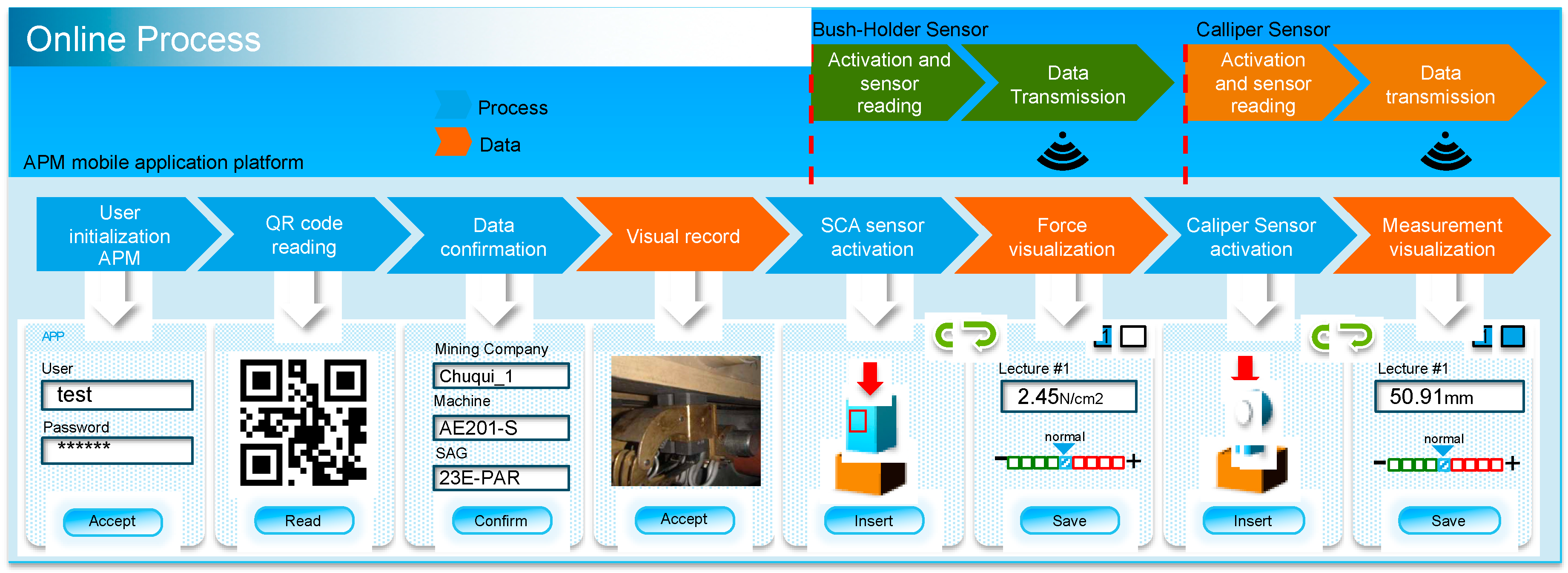
To address the problems described above, this research presents the development of a new integrated monitoring instrument with a control software prototype. Specifically, we present a new sensor to measure the force applied by the spring mechanism, combined with a wireless caliper for taking the axial measurement of the mounting. The process is orchestrated by a control software that is already used for inspecting a motor with brushes of equivalent dimensions to those used in the SAG grinding mill (Figure 2a). The process is controlled by a mobile application that is implemented in App Inventor [14], which collects the information from the sensors by wireless connection and stores the data for each inspection point in a phase called the “online process”. There is also an automatic report generation process (ARG), designed as a desk application, that uses the stored information to generate a report from the automatically read data.
Various small-sized components were designed and integrated to create the system. They are incorporated in a sensor that is inserted in the brush mounting in the brush-holder of the motor. The proposed system has transmission modules, sensors, and a battery system to allow efficient sensor charging/discharging. Below, we present the details of each of the application’s sub-systems and the new automation protocol with its components.
2.1. Starting the Mobile Application and Visual Record
The mobile application (APM) has been designed to facilitate information collection during inspections. It stores the values and sends them directly to the APM, which allows the user to control all the sensors. The first process of the application is the user opening the software. The APM then asks the user to read a QR code [15] located at a strategic point beside the brush mounting that the operator is going to inspect. The data previously entered and stored in the QR code, which contains information on the station, mill, and inspection point, are read by the APM. This is the starting point for the inspection process, and all additional information is incorporated together with the brush-holder’s location (Figure 3).
Once all the above parameters have been accepted, the application asks the user to photograph the inspection point. This information is important, especially if damaged and/or worn parts need to be changed or replaced. The information is stored temporarily in the memory of the mobile device and later uploaded to the cloud when an Internet connection is available. In general, the motors have two or more brush-holders at the same point, so measurements of both are taken until the inspector can physically check whether the measurements are normal or out of the correct range.
2.2. Mounting Sensor (SCA)
The mounting sensor (SCA) is made of Acrylonitrile Butadiene Styrene (ABS), simulating a real brush of similar dimensions and mechanical properties (density 1020 Kg/m3, elastic module: 2e+0009 N/m2). Its function is to measure the force applied by the spring mechanism on the SCA when the latter is fully inserted into the brush-holder. Our prototype uses the Honeywell FSS Low Profile micro sensor fitted in the head of the sensor. It makes tangential contact with the slip ring of the motor in order to sense the force exerted indirectly on the pressure spring (Figure 4).
The system is energized when it is inserted into the mounting because it has a button that makes contact with the internal walls of the brush-holder. When this happens, the micro-controller and the Bluetooth antenna are energized, allowing wireless communication between the sensor and the mobile device programmed with the APM. The application is provided with the antenna connection numbers to facilitate the process. The process is therefore transparent and direct for the user, with no need to pair devices.
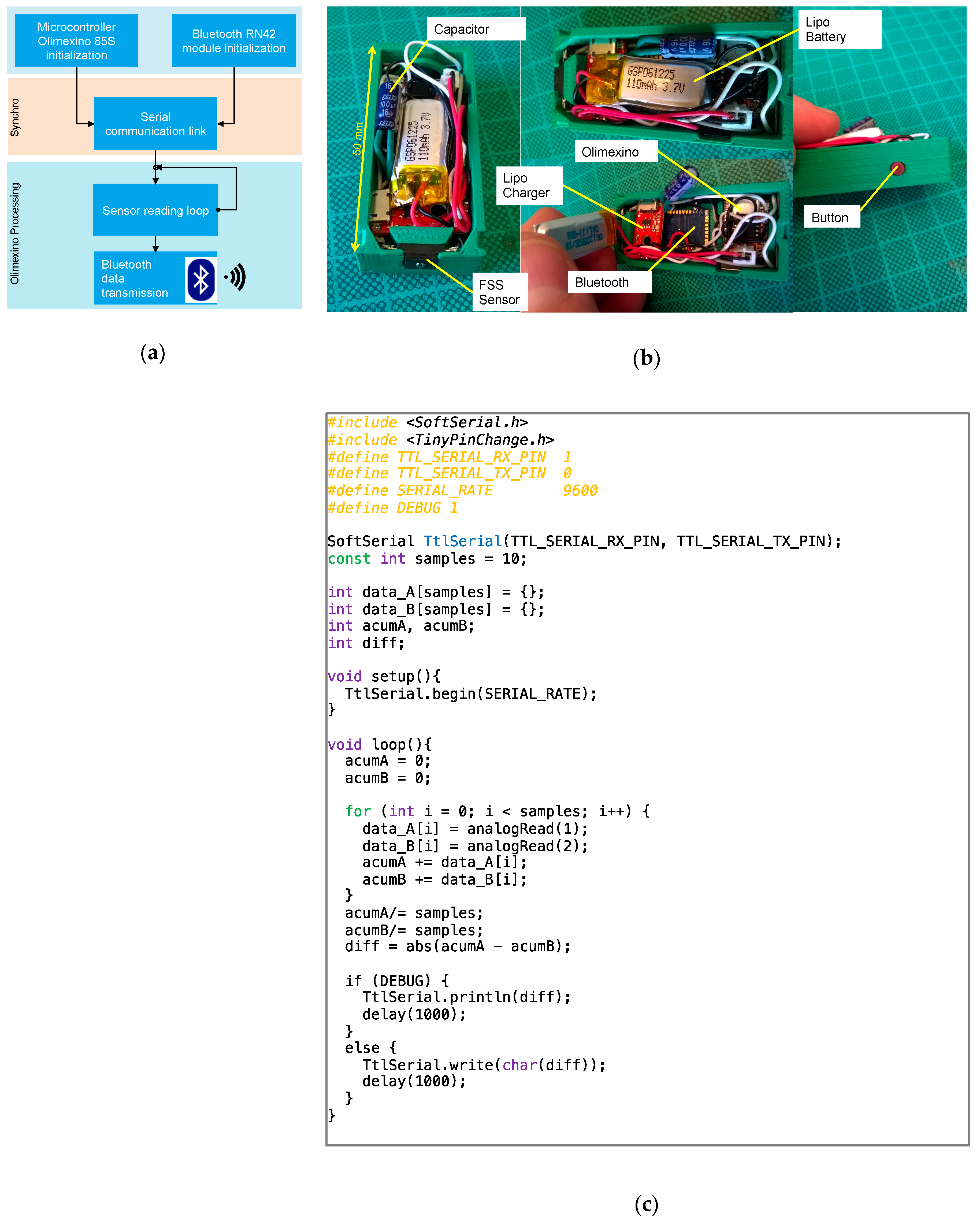
The prototype sensor was configured using the Olimexino 85S micro-controller because it is small with low battery consumption (300 μA) and can operate in a wide temperature range (−45 °C to +85 °C) [16]. According to the flow chart of the program, shown in Figure 5a, the micro-controller activates serial communication with the antenna and then begins to read the force sensor. The sensor takes the moving average of the last 100 readings every 10 ms to reduce measurement errors, since variations may occur at the start of the readings while the mechanical system is stabilizing (Figure 5c).
Once the average measurement has been determined, the digital value is sent to the Bluetooth antenna by serial communication previously established between the mobile application and the sensor. The SMD RN42 antenna receives the value from the micro-controller and sends it on to the APM linked to the sensor. This process occurs through the application while the sensor is inserted in the brush-holder as often as is necessary for the operator to determine if the value found is within the company’s expected tolerances (Figure 5b).
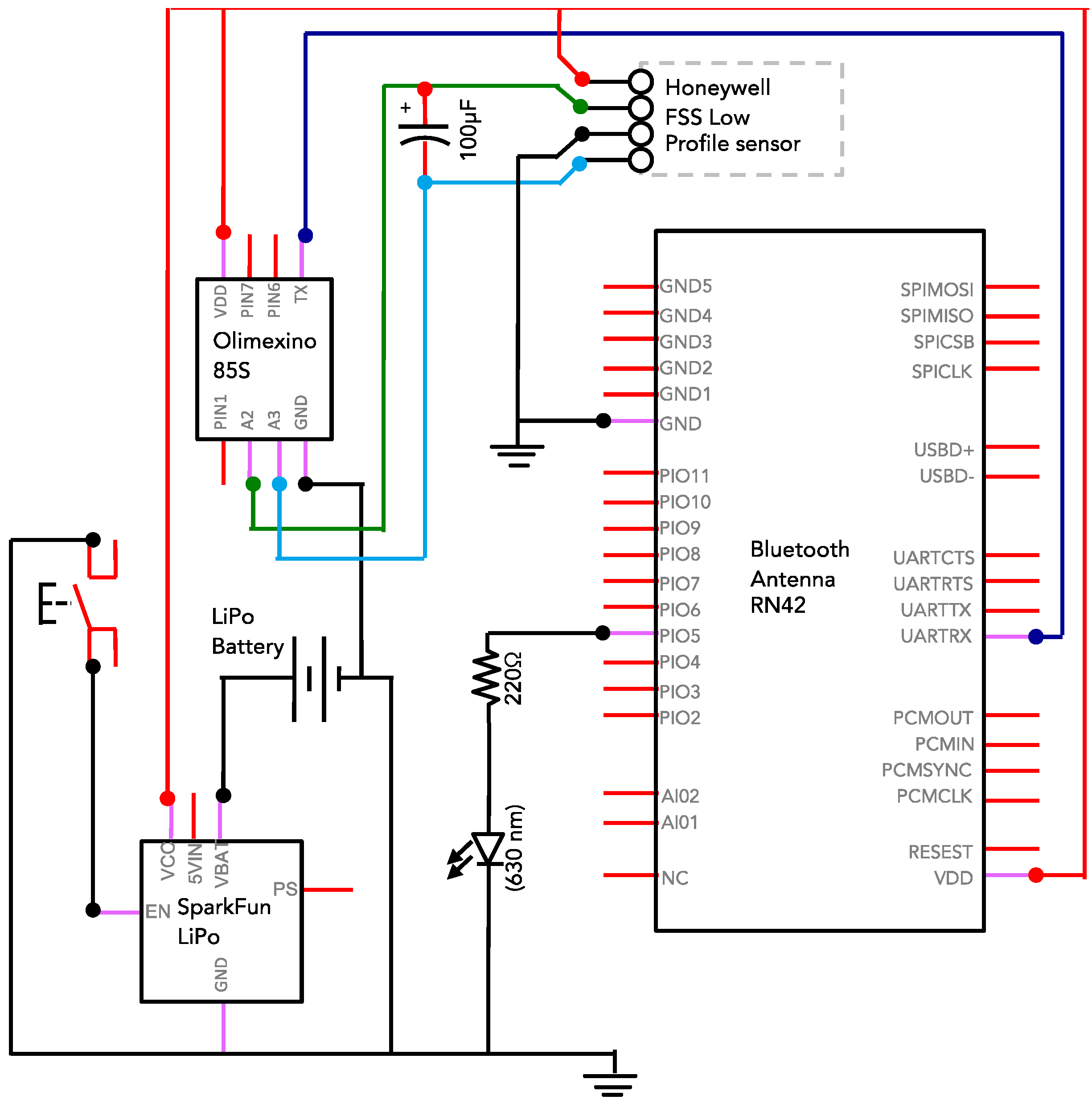
The SCA sensor uses a Honeywell FSS force sensor, with a sensitivity of 0.1 mV/gram. This type of sensor is appropriate for these applications, which require high sensitivity to small changes in the force exerted longitudinally. A capacitor connected in parallel to the sensor is used to filter anomalous signals generated when the sensor is inserted into the mounting. Electric power is provided by a Lipo 110 mA battery, managed by the Sparkfun Lipo Charger Basic plate, and activated by a contact button located on the side of the SCA sensor. This means that the sensor is switched on only when it is inserted into the mounting. With the electricity consumed by the circuit, the sensor can operate for 8 h continuously before the battery is completely discharged (Figure 6).
2.3. Wireless Internal Caliper
Another basic phase of the inspection process consists of analyzing the internal measurements of the brush mounting. The vibrations caused by an incorrect gap between the brush and the brush-holder cause undue wear in both pieces, leading to motor malfunctioning and incorrect, premature wear of the brush, mainly due to changes in its angle within the mounting. Normally, the inspector takes internal measurements of the mounting, which must be done for each pair of brushes and recorded manually. The tolerance of the fit between the brush and the mounting is E10 (ISO-286), allowing a maximum play of 0.075 mm between the pieces. This explains the importance of the precision of the sensors and the correct handling of instruments.
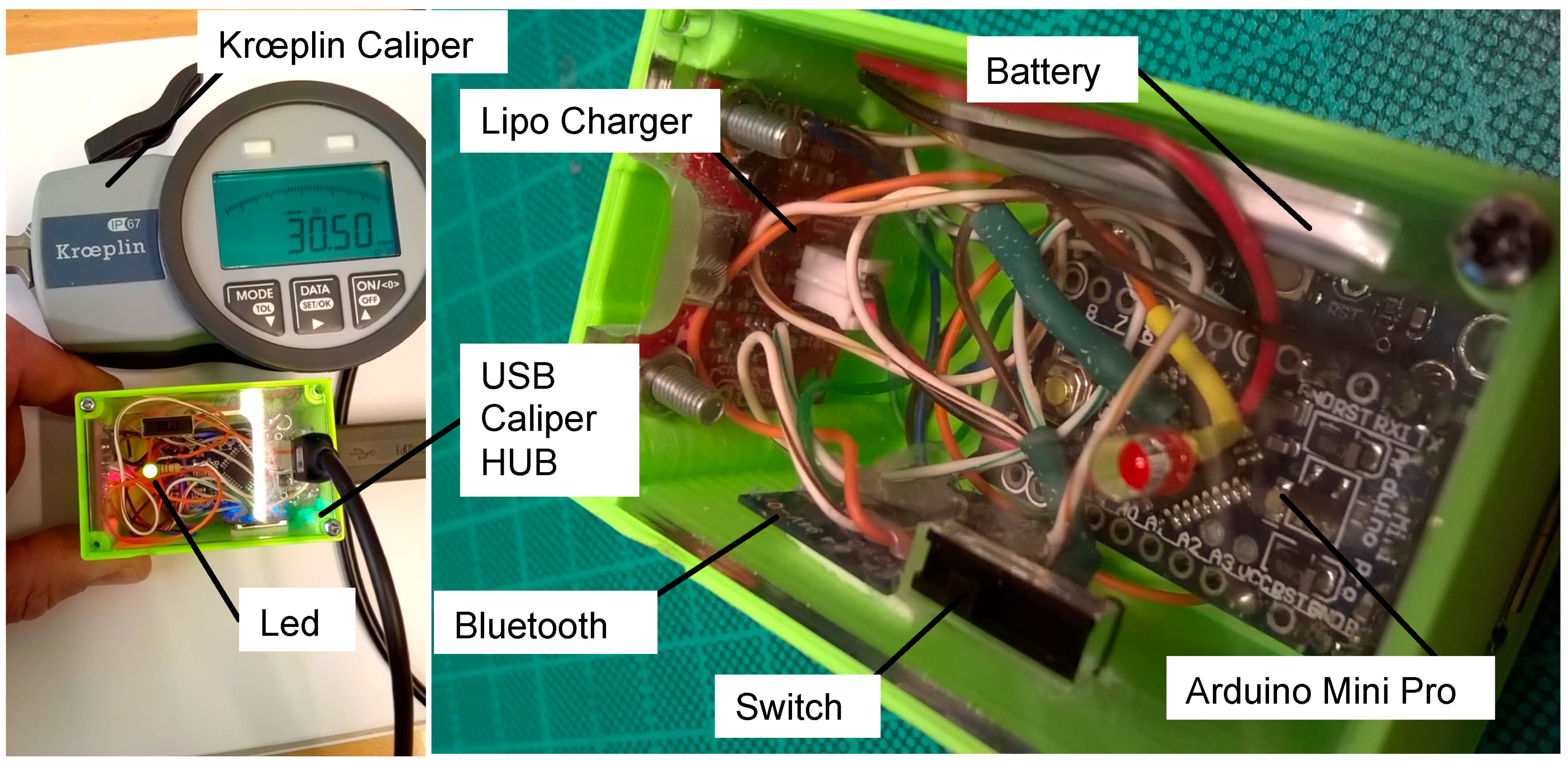
To facilitate inspection, we used a wireless caliper, integrated with the application in the same way as the SCA sensor described above. The Kroepling digital internal measurement caliper was used, which has a keyboard that allows direct handling by the user on the sensor. The procedure for taking the axial and tangential measurements of the brush-holder consists of inserting the caliper into the brush-holder and pressing the OK button of the sensor when it is in the right position for the reading. This allows the inspector to send the information to the application and to view the permitted tolerances. As with the SCA sensor, this process must be carried out in each of the motor’s brush-holders (Figure 7).
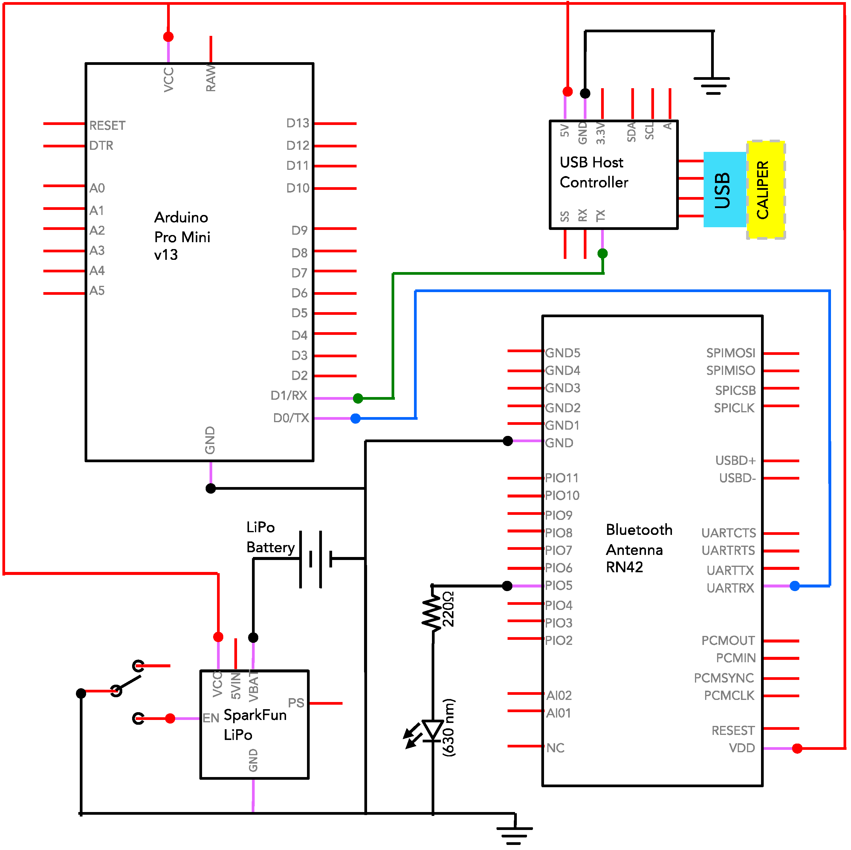
The circuit associated with the caliper enables the application to read the data from the instrument once the user accepts the reading. We used a USB host keyboard reader to read the data sent by the caliper through a USB connection. The data are then processed by an Arduino Pro Mini micro-controller and retransmitted to the Bluetooth antenna. The system has a 500 mA battery, which supports the continuous functioning of the instrument for at least 24 h. Because it uses a LiPo battery, the system has a charging and management circuit and an on/off switch (Figure 8).
3. Results
This section presents the assessment of the properties of the sensor and the SCA sensor calibration system. A physical–mechanical analysis has been prepared to assess their application in industry. The details are given below.
3.1. Analysis of Mechanical Properties
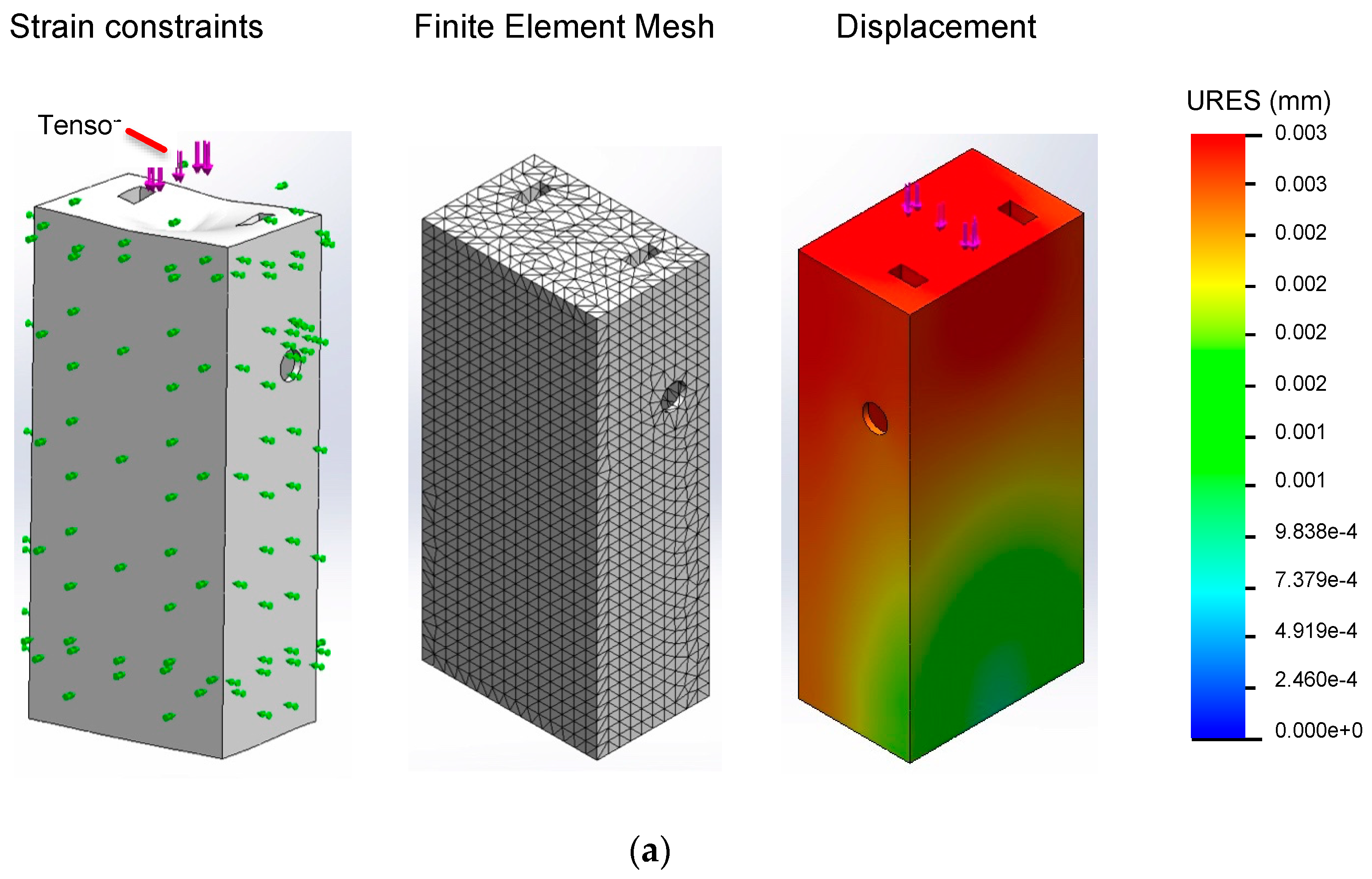
In order to test whether the geometry of the sensor is sufficiently robust not to be deformed by the stresses applied by the spring mechanism, we carried out a modal analysis using the Finite Elements Method (FEM) [17], based on a 3D design and simulating the ABS material. The object was to show that the SCA did not have any play in the mounting, and thus had the same measurement as a brush in its place. The SolidWorks 2014 Software was used for the analysis, which included static analysis using ABS material. For the fixings, we considered four Roller/Slip Control conditions for the walls that make contact with the brush-holder mounting so that movement was only possible radial to the ring, as occurs in reality. We also fixed the face that is in contact with the force sensor in a radial direction (details in Figure 9a).
The external loads are applied in the center of the upper face of the SCA, distributed evenly over a rectangle of 0.5 mm by 1.5 mm. This represents the pivot contact of the spring mechanism with the base of the SCA. The force applied for the correct functioning of a brush with these dimensions, according to the manufacturer’s specifications, is 7.84 N. For the meshes, we used 21,870 high order quadratic elements with 36,446 nodes. The mesh selected was the standard solid mesh with four Jacobian points.
In this simulation, we found that the maximum deformations obtained from the analysis were 0.003 mm (Figure 9b), proving that the mechanical design of the SCA is sufficiently robust not to suffer significant deformation while under pressure by the spring mechanism. We also show a section profile of the deformations obtained from the analysis in the internal parts of the sensor, using a colored scale to highlight the degree of internal displacement (Figure 9c).
3.2. Calibration of SCA Sensor
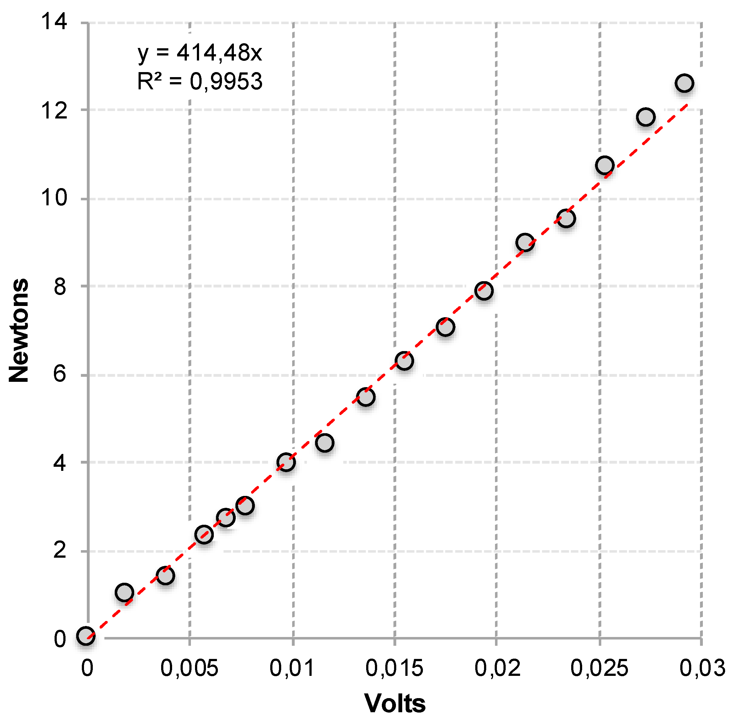
For sensor calibration, a mechanical system connected to a PCE precision dynamometer with a screen read-out was used. Because the force exerted on the sensor varies, the voltage generated by the SCA sensor was recorded along with the value measured by the dynamometer. Each reading was taken with a 10-s pause for each force increment to allow the sensor reading to stabilize. As shown in Figure 10, the results show high precision and stability in the calibration tests done in the laboratory (R2 = 0.995). The SCA sensor was designed to receive a higher load but this does not occur in practice as the forces are smaller than 15 N. Based on this result, the reading procedure integrated into the software of the SCA sensor converts the voltage to a force using the following equation: , a linear model generated by the least-squares method.
4. Discussion
Our research presents the development of two offline motor measurement systems: (1) A wireless SCA sensor that simulates a brush and has similar mechanical properties, and (2) a caliper which has been fitted with a wireless transmission module. Both systems are controlled by a monitoring software that is operated by the inspector. It allows the spring forces and the internal measurements of the brush-holder to be recorded on a mobile platform by wireless Bluetooth technology. The software assesses in real-time, whether the values recorded are outside the standard range or present normal parameters. Once the measurements have been collected, a report generation software is applied using the data stored over one or more days of the inspection.
In order to assess the mechanical and physical capacities of the SCA sensor, the force parameters were measured using a mechanical system calibrated with a force sensor, and the wear and stress parameters were measured using the Finite Elements Method (FEM). The results confirm that the mechanical design of the sensor allows it to correctly measure the spring tension by indirect means since the maximum deformation of the SCA sensor under the stress applied is 0.003 mm. The errors in spring tension measurement caused by elastic deformation of the component can therefore be considered as negligible. Future research will be to design a test brush that can be used while the machine is operating to sense its internal conditions, e.g., temperature, voltage, humidity, and vibrations.
5. Conclusions
Over the last five years, large-scale mining has seen a sustained reduction in profit levels worldwide. For this reason, mining companies are developing new maintenance and control units for inspection processes in order to avoid unplanned stoppages and catastrophic failures. Today, the industry is focusing more on avoiding damage to components than replacing parts and pieces in order to reduce costs and increase the sustainability of their machinery. The inspection of electric motors is a central point of this policy. Unfortunately, current inspection processes are inefficient because they rely on inspector training, which is inevitably subject to human error. Motor inspections are associated with physical, acoustic, and mechanical restrictions. This research has to be planned with extreme care, control, accuracy, and efficiency because the loss of elements inside the motor can result in high operating costs for the companies, in the order of 75,000 USD/h or more, depending on the nature of the fault.
This research presents a newly developed sensor, a new inspection protocol, and a software that orchestrates the system in order to improve the current inspection protocol in electric motors of SAG grinding mills. The proposed system will allow for the automation of tasks that are currently done manually, such as inspection, data collection, parameter evaluation, and report generation. The new inspection protocol is a support tool available to the inspector that will significantly reduce human error, increase measurement accuracy, allow online data storage, reduce inspection times, and facilitate monitoring and control of the various components by allowing traceability of the points inspected. This software can be incorporated as a KPI in mine management systems, since it allows managers to assess the availability levels of machinery, and reduces maintenance times, increasing availability for use.
Author Contributions
Conceptualization, M.C. and F.Á.; methodology, M.C.; software, J.C. and F.P.-C.; validation, F.Á. and R.V.; formal analysis, F.Á.; investigation, M.C. and R.V.; resources, M.C., F.P.-C.; writing—original draft preparation, M.C. and R.V.; writing—review and editing, M.C. and R.V.
Funding
This research was funded by Innova Chile, CORFO, grant number 15VIP-44025.
Conflicts of Interest
The authors declare no conflict of interest.
References
- Sottile, J.; Holloway, L.E. Fault monitoring and diagnosis in mining equipment: Current and future developments. In Proceedings of the 1992 IEEE Industry Applications Society Annual Meeting, Houston, TX, USA, 4–9 October 1992; pp. 2026–2033. [Google Scholar]
- Thomson, W.T.; Fenger, M. Current signature analysis to detect induction motor faults. IEEE Ind. Appl. Mag. 2001, 7, 26–34. [Google Scholar] [CrossRef]
- Gao, Z.; Cecati, C.; Ding, S.X. A Survey of Fault Diagnosis and Fault-Tolerant Techniques Part I: Fault Diagnosis with Model-Based and Signal-Based Approaches. IEEE Trans. Ind. Electron. 2015, 62, 3757–3767. [Google Scholar] [CrossRef]
- Reddy, N.S.; Saketh, M.S.; Dhar, S. Review of sensor technology for mine safety monitoring systems: A holistic approach. In Proceedings of the 2016 IEEE First International Conference on Control, Measurement and Instrumentation (CMI), Kolkata, India, 8–10 January 2016; pp. 429–434. [Google Scholar]
- Uttej, B.; Rao, P.S. Wireless Sensors Based Embedded System for Avoidance of Fatalities in Mines. Int. J. Sci. Eng. Technol. Res. 2015, 4, 3147–3151. [Google Scholar]
- Kumar, M.; Paepcke, A.; Winograd, T. EyePoint: Practical Pointing and Selection Using Gaze and Keyboard. In Proceedings of the SIGCHI Conference on Human Factors in Computing Systems—CHI ’07, San Jose, CA, USA, 28 April–3 May 2007; p. 421. [Google Scholar]
- Ralston, J.; Reid, D.; Hargrave, C.; Hainsworth, D. Sensing for advancing mining automation capability: A review of underground automation technology development. Int. J. Min. Sci. Technol. 2014, 24, 305–310. [Google Scholar] [CrossRef]
- Lee, R.H. The Other Electrical Hazard: Electric Arc Blast Burns. IEEE Trans. Ind. Appl. 1982, IA-18, 246–251. [Google Scholar] [CrossRef]
- Muzaffar, S.; Cummings, K.; Hobbs, G.; Allison, P.; Kreiss, K. Factors Associated with Fatal Mining Injuries Among Contractors and Operators. J. Occup. Environ. Med. 2013, 55, 1337–1344. [Google Scholar] [CrossRef] [PubMed]
- Dudgeon, M. Lockout/Tagout in Mining Seven Tips for Worker Safety. Best Pract. 2013, 58, 70–71. [Google Scholar]
- Lee, J.; Wu, F.; Zhao, W.; Ghaffari, M.; Liao, L.; Siegel, D. Prognostics and health management design for rotary machinery systems—Reviews, methodology and applications. Mech. Syst. Signal Process. 2014, 42, 314–334. [Google Scholar] [CrossRef]
- Lei, Y.; Lin, J.; He, Z.; Zuo, M.J. A review on empirical mode decomposition in fault diagnosis of rotating machinery. Mech. Syst. Signal Process. 2013, 35, 108–126. [Google Scholar] [CrossRef]
- Titichoca, G.; O, L.M. Análisis del problema de medición de nivel de llenado en Molinos SemiAutógenos (in Spanish). Remetallica 2003, 23, 2003. [Google Scholar]
- Wolber, D.; Abelson, H.; Spertus, E.; Looney, L. App Inventor for Android: Create Your Own Android Apps; O’Reilly Media Inc.: Sebastopol, CA, USA, 2011. [Google Scholar]
- ISO/IE-18004:2006. Information Technology—Automatic Identification and Data Capture Techniques—QR Code 2005 Bar Code Symbology Specification; ISO: Geneva, Switzerland, 2006. [Google Scholar]
- Olimex. Olimexino 328: User’s Manual. 2013. Available online: https://www.olimex.com/Products/Duino/AVR/OLIMEXINO-328/resources/OLIMEXINO-328_manual.pdf (accessed on 26 October 2019).
- Bathe, K.J. Finite Element Procedures; Prentice Hall: Englewood Cliffs, NJ, USA, 1995. [Google Scholar]
Figure 1.
(a) Brush-holder and its components; (b) model for mechanical wear versus spring pressure.
Figure 1.
(a) Brush-holder and its components; (b) model for mechanical wear versus spring pressure.

Figure 2.
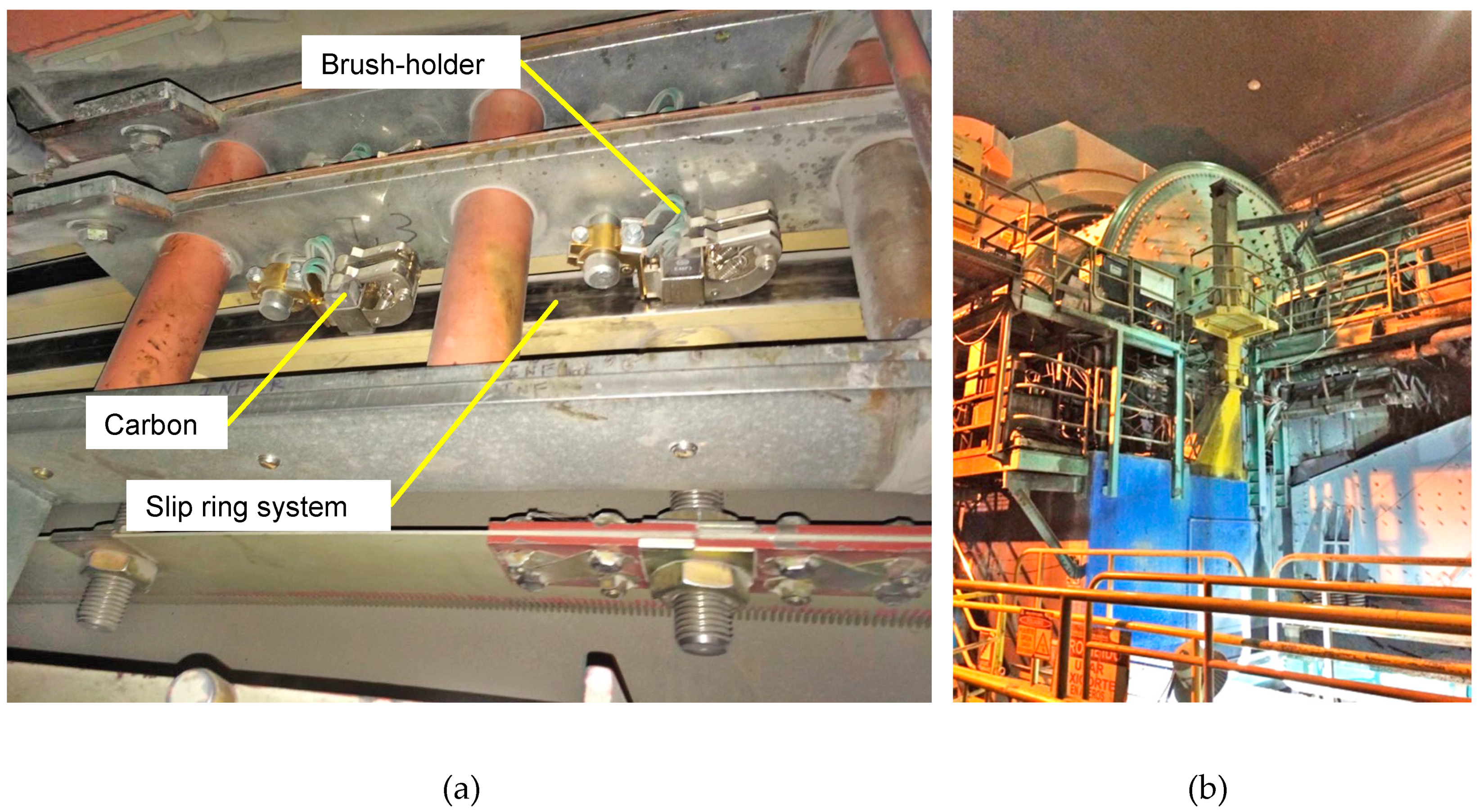
(a) Brush arrangement in the motor of a SAG grinding mill, Codelco, Chile, (b) SAG grinding mill CODELCO, Chile.
Figure 2.
(a) Brush arrangement in the motor of a SAG grinding mill, Codelco, Chile, (b) SAG grinding mill CODELCO, Chile.

Figure 3.
Inspection by mobile application APM.

Figure 4.
Diagram of the brush inside the brush-holder, in contact with the slip ring.

Figure 5.
(a) Data processing in the mounting sensor (SCA); (b) real prototype of SCA sensor; (c) data processing Olimexino SCA sensor.
Figure 5.
(a) Data processing in the mounting sensor (SCA); (b) real prototype of SCA sensor; (c) data processing Olimexino SCA sensor.

Figure 6.
SCA mounting sensor circuit.

Figure 7.
Real model of Caliper USB Hub.

Figure 8.
Caliper USB Host Controller and data sensor circuit.

Figure 9.
(a) Model restrictions and displacements generated by mechanical stresses; (b) section profile subject to mechanical deformations; (c) simulation of sensor deformation through FEM modal simulation.
Figure 9.
(a) Model restrictions and displacements generated by mechanical stresses; (b) section profile subject to mechanical deformations; (c) simulation of sensor deformation through FEM modal simulation.


Figure 10.
Sensor calibration curves and an estimate of Force/Voltage conversion.

© 2019 by the authors. Licensee MDPI, Basel, Switzerland. This article is an open access article distributed under the terms and conditions of the Creative Commons Attribution (CC BY) license (http://creativecommons.org/licenses/by/4.0/).
Share and Cite
MDPI and ACS Style
Carrasco, M.; Álvarez, F.; Velazquez, R.; Concha, J.; Perez-Cotapos, F. Brush-Holder Integrated Load Sensor Prototype for SAG Grinding Mill Motor. Electronics 2019, 8, 1227. https://doi.org/10.3390/electronics8111227
AMA Style
Carrasco M, Álvarez F, Velazquez R, Concha J, Perez-Cotapos F. Brush-Holder Integrated Load Sensor Prototype for SAG Grinding Mill Motor. Electronics. 2019; 8(11):1227. https://doi.org/10.3390/electronics8111227
Chicago/Turabian StyleCarrasco, Miguel, Francisco Álvarez, Ramiro Velazquez, Javier Concha, and Francisco Perez-Cotapos. 2019. "Brush-Holder Integrated Load Sensor Prototype for SAG Grinding Mill Motor" Electronics 8, no. 11: 1227. https://doi.org/10.3390/electronics8111227
Note that from the first issue of 2016, this journal uses article numbers instead of page numbers. See further details here.