
Distributed Intelligence in Autonomous PEM Fuel Cell Control

1
Center for Research, Development and Innovation of Computer Systems (CIDIS)—Faculty of Engineering in Electricity and Computation (FIEC), Escuela Superior Politécnica del Litoral (ESPOL), Guayaquil P.O. Box 09-01-5863, Ecuador
2
Center for Automation and Robotics (CSIC-UPM), Ctra. Campo Real km. 0,200, 28500 Arganda del Rey, Spain
3
The National Hydrogen and Fuel Cell Technology Testing Centre (CNH2), Prolongación Fernando el Santo, s/n, 13500 Puertollano, Spain
*
Author to whom correspondence should be addressed.
Energies 2023, 16(12), 4830; https://doi.org/10.3390/en16124830
Submission received: 3 May 2023
/
Revised: 1 June 2023
/
Accepted: 2 June 2023
/
Published: 20 June 2023
(This article belongs to the Section D2: Electrochem: Batteries, Fuel Cells, Capacitors)
Abstract
:A combination of perceptive and deliberative processes is necessary to ensure the efficient and autonomous control of proton exchange membrane fuel cells (PEMFCs) under optimal humidification conditions. These processes enable monitoring and control tasks across various application scenarios and operating conditions. Consequently, it becomes crucial to adjust parameter values corresponding to different states of the PEMFC during its operation. In this context, this work presents the design and development of an architecture for the control and management of a PEMFC with a maximum power output of 500 [W] based on intelligent agents operating under optimal conditions (membrane humidification). The proposed architecture integrates perception and action algorithms that leverage sensory and contextual information using heuristic algorithms. It adopts a hierarchical structure with distinct layers, each featuring varying time windows and levels of abstraction. Notably, this architecture demonstrates its effectiveness in achieving the desired energy efficiency objective, as evidenced by successful validation tests conducted with different electrical power values delivered by the fuel cell, encompassing three distinct operating states (dry, normal, and flooded). An exemplary application of this scheme is the dynamic control of the humidification of the polymeric membrane, which further highlights the capabilities of this architecture.
1. Introduction
The most severe problems facing humankind, particularly the issue of energy sustainability, must be tackled by the engineering sciences, taking the “bull by the horns”. For this, the hydrogen fuel cell, in the context of the “hydrogen economy”, constitutes a clean energy source with great potential for the present and the future [1,2]. The PEMFC is an electrochemical device that converts chemical energy from fuel (H2) into electrical energy in a single step and produces water and heat as by-products. It exhibits favorable characteristics such as a high-power density, zero carbon emissions, a low working temperature, a fast startup capacity, and varied applications. On the other hand, its main disadvantages, such as cost, durability, performance, and stability, are of high interest in scientific research, given that, to overcome conventional devices, these aspects must be improved through optimizing their operating conditions [3].
Although the PEMFC operation is simple in concept, its electrical behavior depends, among other aspects, on the gas diffusion processes, the homogeneous distribution of H2 and O2 gases in the membrane [4], the mixed electron–proton conduction, the successful development of the anodic and cathodic reactions, and the management of the membrane humidity degree [5]. Excessive water produces stagnation, decreasing the electrical efficiency (H2 is wasted), and the lack of water causes dryness of the membrane, worsens its electrical performance, and shortens the life expectancy of the cell. This electrical response is not linear, with multiple interactions between structural and functional variables, which makes it difficult to establish a precise model to optimize its operation [6].
From the control engineering point of view, the PEM cell presents characteristics such as: (a) a system of control variables to be characterized, which needs a comprehensive set of sensors, and that can be tackled with multiple simple control loops, mainly PID or PI, implemented in distributed systems and having the issue of variable interrelation; (b) strongly coupled subsystems, for instance, the management of the water content inside the cell (humidification degree of the membrane), since its value is modified by variables such as temperature, the humidity of the injected gas, the flow rate used, and even the load connected to the fuel cell; and (c) a lack of precise models of PEM fuel cells and their electrical behavior, making their control highly restricted [7].
Identifying the system to be controlled is fundamental if the control strategies are to be applied successfully. However, it is only viable when the process dynamics are well-defined. In the case of systems with highly variable structures, such as the PEM stack, the usefulness of a reduced model and of the system identification decreases. The interactions inside the PEMFC are so numerous, and at such a low level, that predicting its response is almost impossible. To understand the operation of the cell, taking some measurements is necessary, which in some cases is difficult due to the physical nature of the system [8]. Hence, models and simulations play a vital role, for which we must remember that their complexity and degree of detail are a function of what needs to be understood [9,10].
Models can be detailed at the cell, stack, or system level, and structurally classified as analytic, semi-empirical, and mechanistic. An example is the mass and energy balance model, oriented toward the optimization and control of the PEM cell stack, which includes the analysis of theoretical and semi-empirical electrochemical equations, for which the GPROMS environment was used [11]. Many models combine artificial intelligence algorithms to simulate the operation of a PEM cell stack, such as the distributed deep reinforcement learning algorithm, using parallel computing technologies and the software tool for real-time simulation RT-LAB, MATLAB/SIMULINK 2016b [12]. Others are combined with mathematical models solved by numerical methods [13] or statistical tools [14].
One of the main difficulties in defining an intelligent system lies in the various intelligence concepts. At a minimum, intelligence requires the ability to perceive (agent) and adapt to the environment (learning), make decisions, and perform control actions. From the point of view of control theory, intelligence can be defined as integrating knowledge and feedback into the control system to plan and generate actions to achieve an objective. The term “intelligent control” is closely related to “autonomous control”, as it has a high degree of autonomy when tending towards its control objectives. In many intelligent control systems, the controller design methodology is essentially heuristic and based on certain principles of artificial intelligence; such methodologies are very varied and include fuzzy logic, rule-based control, artificial neural networks, genetic algorithms, and learning algorithms, etc. [5].
Considering that many studies conclude that their results are precise, the truth is that, whilst search capacity and efficiency have improved, precision is still a subject for analysis. Some studies only partially simulate different controllers with specific control objectives, leaving deficiencies in precision, stability, and robustness, which need to be addressed and improved [14]. These weaknesses constitute a challenge and allow us to establish the objective of this study. To optimize the comprehensive response of the PEMFC, a control model based on intelligent agents of perception and action is proposed as the most appropriate control methodology for achieving the objectives. It is a hierarchical model with several levels of competencies, which gravitate around a global representation of the PEMFC, and where each level is made up of a set of specialized agents that integrate expert knowledge and strategies for the local and global control of variables and subsystems, resorting for accomplishing this, in some cases, to the use of intelligent control techniques.
After this introduction, this study is organized into the following sections. The state-of-the-art scenario analyses the precision and reliability of the different control systems to optimize the response of the PEMFC. The study scenario explains the main parameters and elements used for the data collection, characterization, and validation of the perception and control strategies that a human expert would follow in the system control. Subsequently, the concepts are detailed in the proposed control model section, where the intelligent agents of perception and action are presented, including a description of the techniques and models implemented. In the results and discussion section, the results obtained in the autonomous operation of the PEMFC stack are explained in detail, both at the basic level of operation and the control of the optimal operating setpoint. Finally, this work ends by presenting some conclusions and possible future work.
2. State-of-the-Art Review
Linear controllers, such as proportional–integral (PI), proportional–integral–derivative (PID), proportional–derivative (PD), quadratic–Gaussian (QG), etc., perform well if the system is linear but have limitations in nonlinear systems. PID control is widely utilized in fuel cell stacks due to its simple structure and high reliability, effectively enhancing system stability and efficiency. Currently, these weaknesses are counteracted with artificial intelligence algorithms applied to adjust its parameters [15]. An additional advantage is that such algorithms enable the extraction of patterns that would be difficult to obtain through other means, often due to high computational or experimental costs.
An example of the above is adaptive PI control using a Morlet adaptive wavelet neural network (single layer) for an experimental 1 kW PEMFC as a mobile power source, the results of which were more accurate than those obtained with the multilayer perceptron neural network [16]. Similarly, fractional order PID controllers (FOPID) have been proposed for the fuel cell air supply system. One is based on a non-linear unknown input observer, which allows for the regulation of both the oxygen excess ratio (OER) and the cathode pressure to desired values [17]. The following is a fuzzy FOPID optimized with the neural network algorithm. Due to its robustness, it allowed for, in addition to the regulation of the OER, the improvement of the transient response and maximization of the output power [18].
Another way to overcome PID response time and accuracy limitations is through using adaptive controllers (APCs). The APC control is highly precise because it allows the updating of the parameters of the non-linear systems in real time and, in the PEMFC, it prevents starvation and potential damage to the membrane. Its disadvantages are its complexity, low dynamic performance, and excess of data and parameters necessary for its precision. To overcome these weaknesses, other alternatives have been developed, such as robust adaptive controllers (RAC) [19,20], model reference controllers (MRC) [21] included in automotive applications [22], adaptive controllers with data-oriented artificial intelligence [23] or neural networks [4,15,16,24], and adaptive schemes based on fuzzy logic to control the flow of gases [25], especially OER [20].
Fuzzy logic control (FLC) has a timely response, a simple structure, and is easily combined with other controllers. Its disadvantage is that, by definition, it suffers from a systemic approach, and its optimization cannot be guaranteed. Among the different types of FLC, we can find the fuzzy logic control of the PID type (FPID) and the adaptive fuzzy logic control (AFLC).
Robustness refers to the ability to reject noise signals, making it a crucial quality in control systems. Robust control techniques aim to counteract time-varying disturbances effectively. The commonly employed approaches include optimal control methods, such as H2 and H∞, which rely on solutions obtained from algebraic Riccati equations and linear matrix inequalities. In the context of proton exchange membrane fuel cells (PEMFC), sliding mode controllers (SMC) are extensively utilized, as they facilitate the achievement of a stable state known as the sliding surface. However, the presence of a phenomenon called chattering can diminish the performance of SMC.
An application of the dynamic model of the PEMFC is an approximate linearization using the Taylor series with Jacobian matrices and whose error, when perceived as a disturbance, is compensated by the robust control loop H-infinity, which requires the Riccati solutions. The model rejects the disturbance in the PEMFC fuels; its stability is demonstrated by Lyapunov analysis and confirmed by simulation experiments [26]. In the H-infinity control line, the design of a controller for a DC–DC converter, with applications to the power train of an electric vehicle, has been sought [27]. Other work includes an optimal linear parameter variation (LPV) technique applied to parameter optimization [28].
As for the SMC controller, especially for improving the OER, there is a cascaded adaptive integral terminal-type slider-mode control based on a time delay estimation algorithm (cascaded AITSMC-TDE), the stability of which is verified by Lyapunov analysis [29] for the super torsion algorithm [30,31]. Other SMC controllers have been used to improve the lifetime of the PEMFC [32,33].
Observer-based control has high robustness; however, it is significantly dependent on large amounts of data that increase the complexity of the system and its computational cost. On the other hand, model predictive control (MPC) is closely combined with neural network models and artificial intelligence algorithms to improve its accuracy. Unfortunately, its complexity is time-consuming, and its accuracy depends on the model. On the other hand, fault-tolerant control (FTC) is based on fault monitoring, so its design is valid for the specific case being analyzed. It consists of multiple controllers to achieve its control objective, thus incurring complicated configuration and high computational costs.
In addition to controlling the selected variable, optimal control seeks to minimize costs and maximize profit, allowing for high precision and a simple structure. However, it has two drawbacks that limit its use: the first is that the disturbances caused by noise, environmental factors, or errors in the measuring instruments are outside of this type of control, and the second is that, as it is based on a search optimal, the driver could focus on local rather than global optimization.
Artificial intelligence control has a fast response and high precision. However, its applicability is low due to its complexity and the large amount of data required. The solution to the problem would be to combine the traditional methods and use free software as a heuristic algorithm. For this reason, CFD simulation techniques, physical models, and validated experimental models are used to extract the data. Notably, many neural network models for PEMFC control and diagnosis use exponential activation functions [34].
An example of the application of artificial intelligence in the PEMFC is airflow control, which directly affects the oxygen excess ratio (OER). Insufficient oxygen results in a reduction in the PEMFC voltage, while excessive oxygen leads to an increase in parasitic power. To enhance the OER, an adaptive proportional integrative (PI) controller is designed and tuned using an algorithm based on distributed deep reinforcement learning, named multi-role exploration strategy distributed deep deterministic policy gradient (MESD-DDPG) to improve the OER. The simulation results demonstrate the adaptability and performance of the MESD-DDPG real-time adaptive PI controller, showcasing its potential responsiveness under various working conditions [12,35].
Another example is a configuration that optimizes the PEMFC system by controlling the output voltage. To achieve this, the DC/DC converter is improved by redesigning the LQR linear quadratic regulator with a version of the whale optimization algorithm, which has been improved using chaos theory (OICWOA). The simulated results showed higher efficiency than other methods from the point of view of ripple current and overshoot [36].
Some other examples of artificial intelligence have been applied to optimize the PEMFC, focusing on obtaining its parameters. One notably accurate model is based on the Levenberg–Marquardt backpropagation (LMBP) algorithm of artificial neural networks (ANN). The performance of this model was compared to four typical metaheuristic algorithms, and simulated results indicated that the LMBP identifies parameters with a speed of 95.9% and an accuracy of 99.8% [37].
Another method utilized is the crow search algorithm (CSA), which is based on the behavior of a crow population. This algorithm is relatively simple and easy to implement, requiring only two tunable parameters. It proves to be suitable for engineering design problems with various objective functions, constraints, and decision variables. An improved version of this algorithm aims to minimize the output voltage error, enhance the search speed, and prevent entrapment at the local minimum [13,38].
In the pursuit of optimizing the acquisition of cell parameters to control the output voltage, models based on hybrid and metaheuristic neural networks have been developed. These include the butterfly optimization algorithm (BOA) and its enhanced counterpart, the monarch butterfly optimization algorithm (MBOA). The algorithm comprises three phases: initialization, search, and termination. It boasts easy implementation, low computational complexity, and the MBOA exhibits improved exploratory capacity while addressing slow and premature convergence [13,39]. Another metaheuristic algorithm is the artificial bee colony (ABC) and its improved version, the artificial bee colony with differential evolution (ABCDE). ABC, through self-organization, incorporates positive feedback, negative feedback, fluctuations, and multiple interactions; it is easy to implement and requires few parameters. ABCDE further enhances the exploration ability. While ABC struggles with complex problems and tends to exhibit slow and premature convergence during the search stage, ABCDE addresses these limitations and achieves improved precision. The algorithm is generally suitable for both single-modal and multimodal numerical optimization problems [40].

Table 1.
Summary of research work to improve the operation of the PEMFC.
| Control Technique | Control Objective | Improvement Achieved | Comments | C-A-R |
|---|---|---|---|---|
| PID | ||||
|
|
|
| 2-3-2 [16] |
|
|
|
| 2-3-2 [17] |
|
|
|
| 3-4-4 [18] |
| FLC | ||||
|
|
|
| 2-4-5 [20] |
|
|
|
| 2-4-3 [25] |
| Robust control | ||||
|
|
|
| 2-3-3 [26] |
|
|
|
| 3-2-5 [28] |
|
|
|
| 2-3-3 [29] |
|
|
|
| 3-3-4 [30] |
|
|
|
| 3-2-5 [31] |
| Artificial intelligence | ||||
|
|
|
| 2-5-4 [12] |
|
|
|
| 2-4-4 [35] |
|
|
|
| 2-5-4 [36] |
|
|
|
| 3-4-4 [38] |
|
|
|
| 2-4-4 [39] |
|
|
|
| 3-4-4 [40] |
|
|
|
| 3-4-4 [41] |
Additionally, another algorithm classified in the swarm category is the coyote algorithm (COA), which has an approach based on the social structure and the exchange of experiences among coyotes. It has only two parameters, it is easy to implement, and its response is stable and accurate. It is suitable for small-scale multimodal optimization problems but, unfortunately, its restriction to convergence towards the global optimum limits its application to the solution of complex engineering problems [13,42].
For the detection of faults in the PEMFC, techniques based on artificial intelligence have the advantage of being non-intrusive. These techniques involve electrochemical impedance spectroscopy, cyclic voltammetry, or galvanostatic analysis. One investigation in this field conducted forecasts of the PEMFC under dynamic load conditions, carrying out a comparative study of three models that represent approaches based on regression (Gaussian process regression), classification (support vector machine), and neural network (artificial neural network). The regression model yielded the best prediction results [42]. Similarly, another study employed an algorithm called XGBoost-Boruta to improve the feature selection and prediction of the PEMFC system [43].
Furthermore, research has focused on the application of artificial intelligence to improve the materials used to build the catalysts, the MEA, the flow channels, or the subsystems that help the proper functioning of the battery [44].
Table 1 summarizes the research works that have been mentioned in this document, adding an intuitive rating between 1 and 5, where 5 is the highest value in complexity (C), accuracy (A) or robustness (R), of the control technique used.
3. Materials and Methods
3.1. Research Scenario
3.1.1. The Proton Exchange Membrane Fuel Cell PEMFC
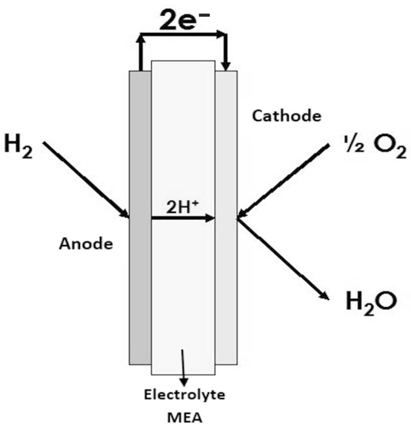
From a physical standpoint, a PEMFC consists of two chambers: pure hydrogen/oxygen that comes from a cylinder, separated by the electrolyte (polymeric membrane) that is in direct contact with the catalyst on both sides, anode/cathode. Its operation is based on two electrochemical reactions: (a) partial oxidation of H2 at the anode, the H2 molecules dissociate in the presence of the catalyst, generating protons (H+) and electrons (e−). The (H+) crosses through the membrane from the anode to the cathode. The (e−) of the anode cross to the cathode through the external electrical circuit generating an electrical current. (b) Partial reduction in O2 at the cathode, in the presence of the catalyst at the cathode, (H+), (e−), and O2 unite, generating H2O and heat as a by-product [45], as shown in Figure 1.
3.1.2. System Experimentation
The tests were conducted with a PEMFC (single cell) and a small 100 W stack (joining several single cells) with platinum-catalyzed carbon cloth electrodes, 0.58 mg Pt/cm2, and an active area of 5 cm2. The assembly was carried out with two types of seals: one made of silicone (1 mm) and another thinner one made of Teflon (0.2 mm) to cover the thickness of the central area. In this manner, the bipolar plates are not pressed on the electrode and do not lose the corrugated part. One of the most relevant characteristics is the use of corrugated stainless steel sheets as bipolar plates [46]. The advantage it presents over other types of bipolar plates is the ease of production since, once the fabrication matrix has been built, the sheets are manufactured in short periods. Nevertheless, the manufacture of graphite or stainless steel bipolar plates requires computer numerical control (CNC) machines and highly qualified personnel, which increases their manufacturing time and cost.
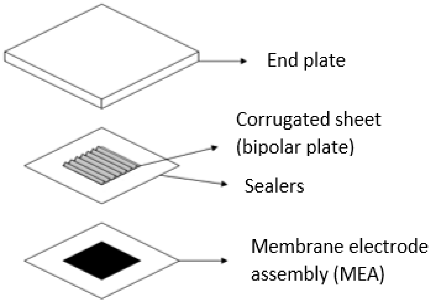
Figure 2 schematically shows the components of the upper half of a PEMFC, being symmetrical with respect to the membrane, and those of the lower half. The electrode–membrane assembly is usually performed by hot pressing and is called membrane electrode assembly (MEA). The surface of the electrodes coincides with that of the corrugated sheets, and both are inside the seals (Teflon gaskets with gas inlet and outlet), while the membrane on the outside also acts as a seal. Table 2 presents the different components of the PEMFC, from top to bottom, with respect to its assembly.
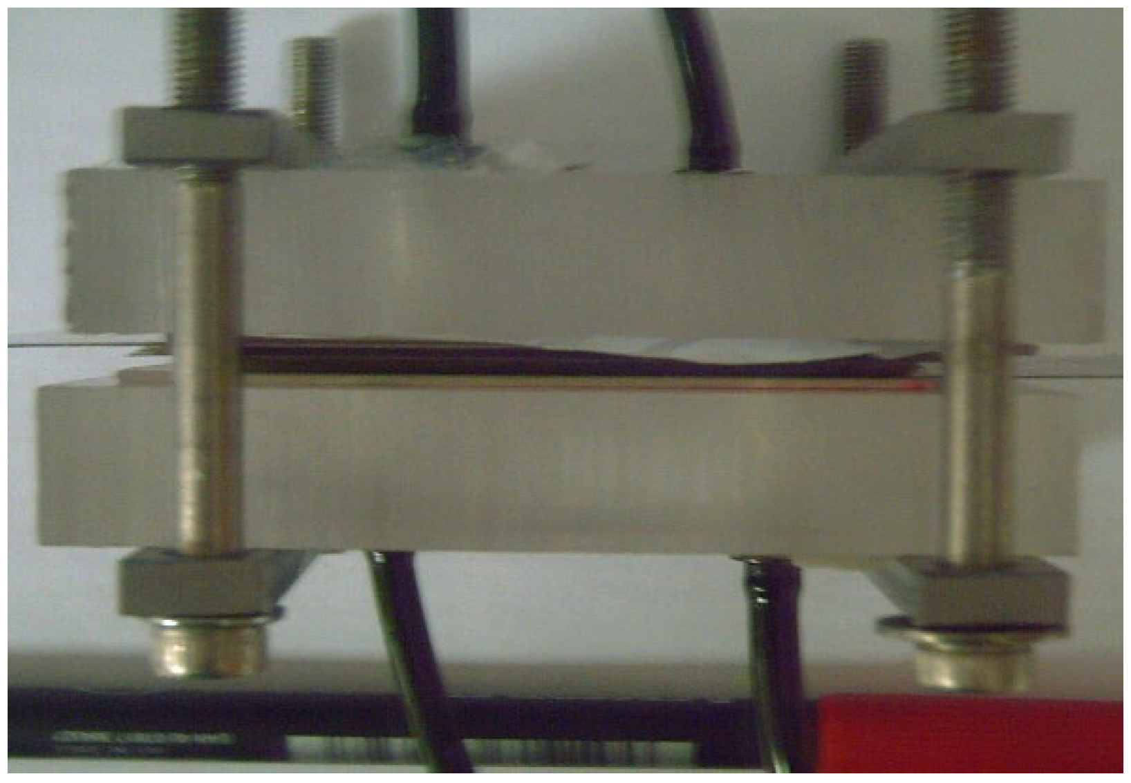
Figure 3 shows an image of the PEM fuel cell stack final assembly. In the assembly, all the necessary parameters and requirements have been considered to guarantee good tightness and thus achieve efficient behavior.
To implement the characterization, control, and validation tests of the approximate reasoning algorithms in the autonomous control of the PEMFC, an integrated measurement and flexible control system is used, with a detailed explanation in [46]. Among the main attributes that this integrated PEM stack measurement and control system incorporates, in relation to other systems detailed in [47,48], we can find the following features:
- Programmable electronic load AMREL ZVL 100-10-20L that optimizes performance, both for characterization studies and new applications.
- Modular, compact, and economic system that can work for PEM hydrogen fuel cells and direct methanol cells of different powers.
- System with open control architecture, flexible to changes, such as increment of variables to be controlled and incorporation of new control algorithms, such as performance management; this allows for autonomous operation of the PEM stack.
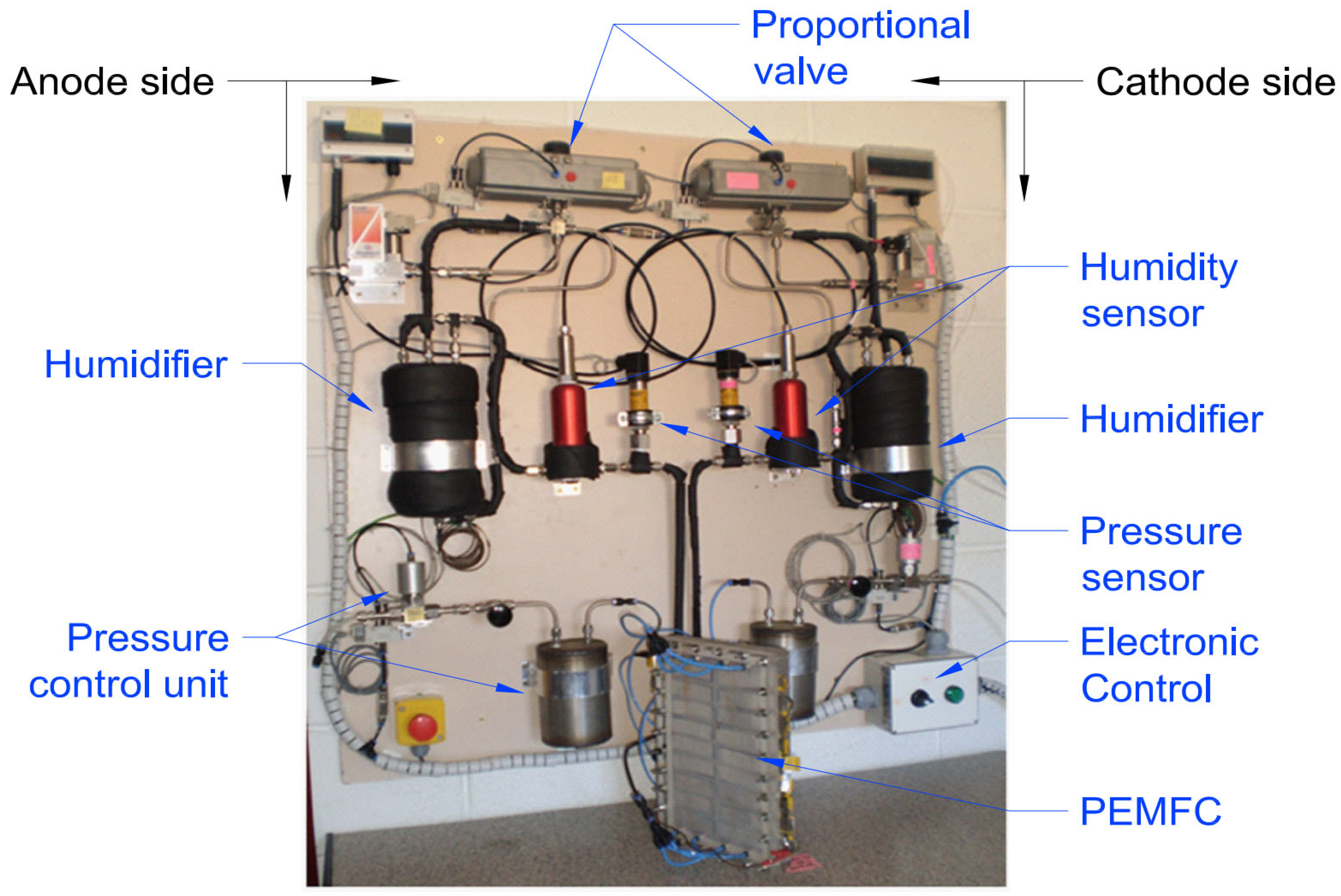
In summary, this is an integrated automated system for the control of PEMFCs with a maximum power output of 500 [W], equipped with the automatic action mechanisms and monitorization of state variables required for the generation of knowledge and smart decision-making, as depicted in Figure 4.
3.1.3. Variation of the Electrical Resistance of the Membrane
Knowledge of the variations in the degree of membrane humidification through changes in the electrical resistance (Rm) is crucial for achieving autonomous control and maintaining optimal operating conditions of the PEMFC. These variations in Rm result from changes in state variables such as temperature, humidity, and gas flow.
In this context, it is proposed to obtain an equivalent electrical circuit by complex impedance spectroscopy (CIS) when the same type of gas is supplied to the PEM fuel cell on both the anodic and cathodic sides, this study being an extension of the work presented in [49]. As these are “symmetric mode” gas supply conditions, the operation of the PEMFC is not associated with the electrochemical reaction of generating energy and water as a by-product, which ensures that the changes observed in the degree of membrane humidification (membrane electrical resistance) are due exclusively to changes made by state variables. In fact, the humidification and the temperature of the gases control the water balance in the PEMFC. In [50], a review of the use of spectroscopy in the measurement, the monitoring, diagnosis, and optimization of PEMFCs is conducted, analyzing different methods based, or not, on models. In [6], it is pointed out that the conductivity of the membrane is directly related to the water contained in the PEMFC and depends on the water transported by the humidified gases. Finally, in [51], an electrical circuit for PEMFC is modeled that uses a parallel resistance that is a function of pressure and temperature.
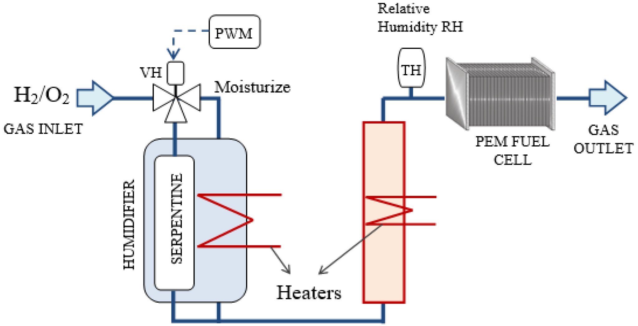
In this work, the system used to characterize the membrane in “symmetric mode” corresponds to the bubbling and coil method, and contributes to the integrated measurement and control system detailed in [46]. The bubbling system passes the gas through a tank (humidifier) with deionized water, Figure 5.
3.2. Proposed Control Model
3.2.1. Knowledge Structure
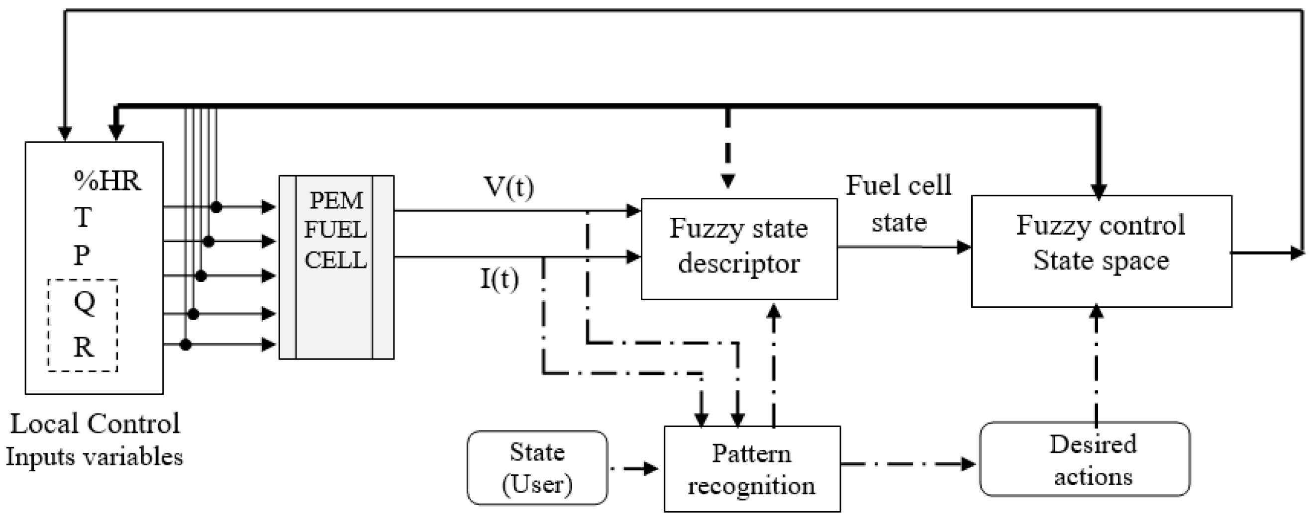
The smart and autonomous operation of the PEM fuel cell under optimal operating conditions requires the characterization, identification, and real-time control of the operating state (estimation of the amount of water contained in the membrane) of the PEMFC. For the perception of the operation state, a qualitative model is implemented using a fuzzy weighted average and, for state control, a closed-loop fuzzy controller is utilized (Figure 6). The use of approximate reasoning techniques both in the perception and in the control of the operation state of the PEM fuel cell is considered a good solution, not only because it is adequate to model the non-linearity inherent to the system.
Perception and control abilities have been encapsulated in intelligent agents. The term agent has been controversial in multiple fields, especially in artificial intelligence (AI), computer science, and control systems. In this paper, the term “agent” is defined as the basic unit of knowledge organization and control architecture, understood as “a process or set of processes aimed at achieving or maintaining an objective, with perceptual, deliberative, and acting abilities, without restriction in its complexity and communication via message passing or shared memory’’ [14]. This work defines two types of agents depending on their processing: perceiving and acting agents. Three fundamental aspects are distinguished in these agents:
- Computing processes or algorithms based on approximate reasoning that define its competence.
- Variables or parameters required or shared in global memory.
- Inputs and outputs associated with the intelligent agent.
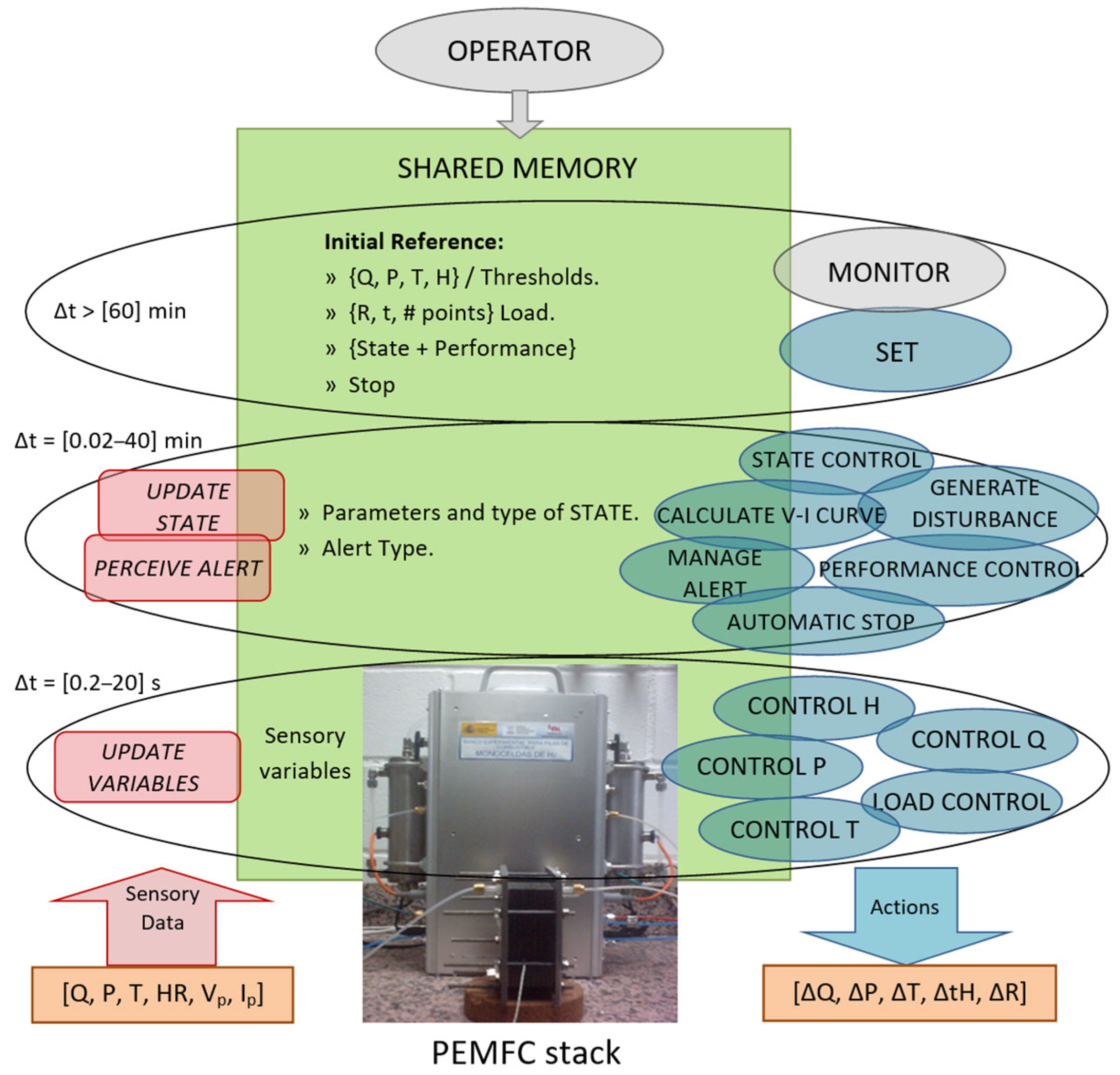
Agents have been organized hierarchically so that each agent initiates the execution of those whose functions it needs, thus allowing the reuse of agents and facilitating the inclusion of agents with new skills. A global representation segmented into three levels of competencies of the intelligent agents involved in autonomous control under optimal humidification conditions of the PEMFC is shown in Figure 7. The blue and grey ellipses, located to the right of Figure 6, correspond to the acting agents. The perceiving agents are rectangles with rounded corners in red, located on the left. In the center of the image in green, the content of the shared memory is displayed. The shared memory contains the global variables necessary for the agents, both acting and perceiving, thus acting as an asynchronous communication channel between them. The input and output signals of the agents correspond to the activation signals that come from, or are directed toward, an agent necessary to start the execution cycle.
The description of the hierarchical structure organized by tasks (perceiving and acting agents) begins with the lower layer. This layer consists of the perceiving agent “UPDATE VARIABLES” and the basic acting agents “CONTROL P, Q, T, H, and LOAD”. These agents correspond to the low-level controllers in the microprocessor network and are in direct contact with the sensors and physical actuators. They share a short-range instantaneous temporal representation of [0.2–20] seconds, which is necessary to maintain stable operating points.
The next layer, known as the intermediate layer, consists of the perceiving agents “UPDATE STATE” and “PERCEIVE ALERT”, as well as the acting agents “CONTROL STATE, CALCULATE V-I CURVE, PERFORMANCE CONTROL, GENERATE DISTURBANCE, MANAGE ALERT, and AUTOMATIC STOP”. These agents have a medium-range temporal representation of [0.02–20] minutes, which is necessary to apply stimuli to the fuel cell stack and wait for its stability to collect data. The perceptive and deliberative processes in this layer leverage the abilities of the agents in the lower layer, providing increased flexibility to the overall architecture. For instance, the agents “CALCULATE V-I CURVE” and “GENERATE STIMULUS” rely on the capabilities implemented in the basic agents “LOAD CONTROL” and “Q CONTROL”. Furthermore, this layer allows for the integration of new agents with skills and algorithms to validate or experiment with novel designs of PEMFCs.
The acting agents “MONITOR” and “CONFIGURE” are located in the upper layer, which has a higher degree of abstraction and a temporal range of [>60] min. These agents possess deliberation mechanisms and use a language (vocabulary and syntax) such as that of the OPERATOR. This similarity facilitates communication through the human-machine interface used to configure the experiment according to the defined objectives (maximum power, material durability, etc.) and the size of the PEMFC (electrical power generated).
In the knowledge structure, perception is articulated around a set of intelligent perceiving agents designed to detect aspects considered key to achieving objectives. These agents implement perception processes to extract relevant characteristics from the system, which the acting agents then utilize. Updating the representation of a given aspect is the responsibility of the perceiving agents that generate it. The action is materialized through the acting agents which, throughout a sequence of activations, generate the control actions over the operating variables of the PEMFC. The term acting agents, in their active state, implies that action decisions are made, either on the physical actuators or on the alert status of other agents.
3.2.2. Intelligent Agents for PEMFC Autonomous Control
The development of new applications or the validation of new components of PEMFC requires the characterization of their electrical response under specific conditions, both of operation (state variables) and power to be supplied (variation of the electric load), as well as humidification of the membrane (operating state of the PEMFC considered normal). Under this context, a set of specific agents have been designed and implemented following the generic design guidelines proposed in the knowledge structure.
Agent PERCEIVE ALERT
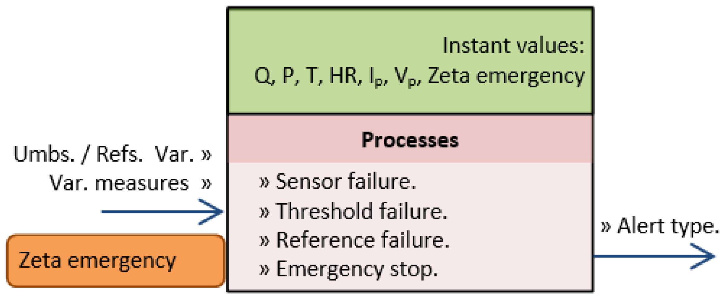
The agent has the following inputs: the measured variables, emergency stop signal, and, from the global memory, the thresholds and references provided by the OPERATOR, and, as output, the type of alert (Figure 8).
In the design of the calculation algorithm, we have considered, on the one hand, the characteristics of the sensors used—that is, the measurement intervals, resolution, and response time—and, on the other hand, the minimum and maximum values that the measurement can take, so that irreversible damage does not occur in the PEM fuel cell or other devices in the installation. These characteristics allow us to estimate four types of alerts, whose estimating functions are shown in Table 3.
Here, Vi stands for the operation variables: flow rate, pressure, humidification, temperature, and stack voltage level; (Lower Limit)fs and (Upper Limit)fs are the limits of the measurement interval of the sensor corresponding to each operation variable and (Lower Limit)Thr and (Upper Limit)Thr correspond to the thresholds. VRef,i stands for the reference value of each variable, and Δt is the time elapsed until the variable reaches the reference.
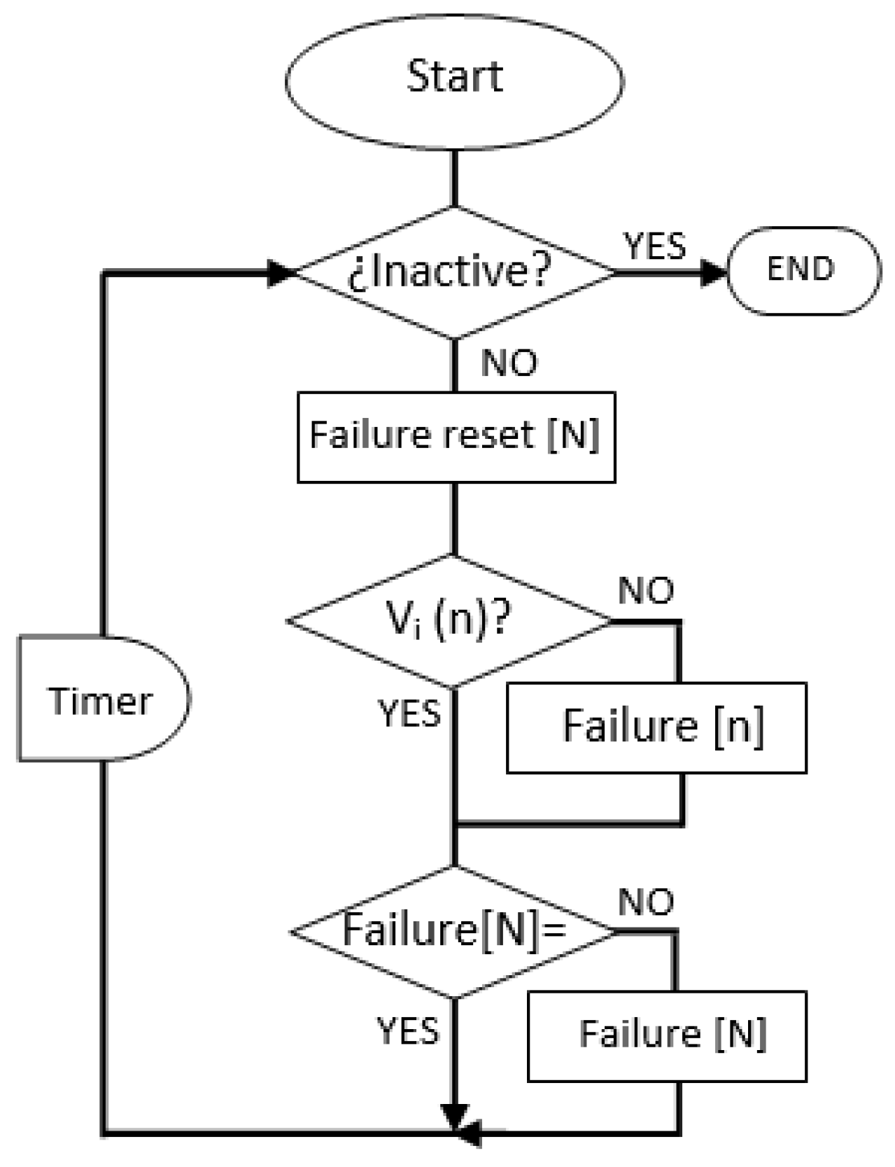
The flowchart of the information in the agent PERCEIVE ALERT is depicted in Figure 9. Where “N” stands for the total restrictions that each variable must meet and “n” is the restriction to analyze; “n” takes values from Table 3 [1,2,3,4]. The time of the operation cycle of the PERCEIVE ALERT agent is determined by the frequency of the readings provided by the sensors. In this case, the PERCEIVE ALERT agent is executed in each control cycle and is in charge of updating the alert type output variable in shared memory.
Agent UPDATE STATE
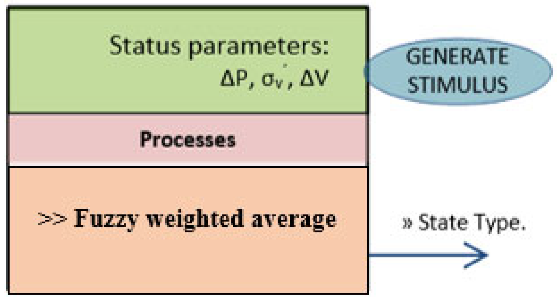
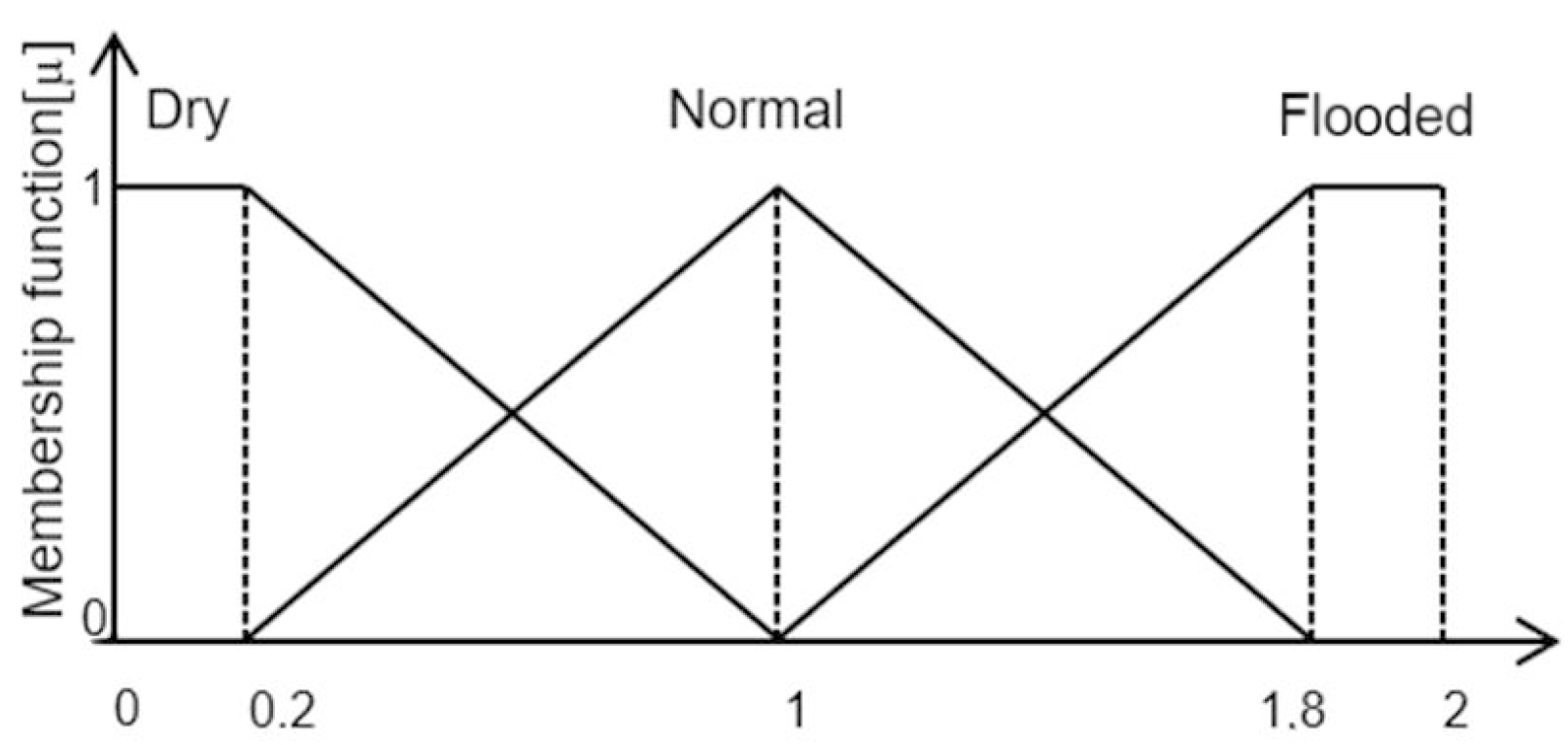
The agent takes, from the global memory, the state parameters {slope change ΔP, moving standard deviation , and voltage increment ΔV}, provided by the GENERATE STIMULUS acting agent when activated within the perceiving agent UPDATE STATE. These state parameters correspond to patterns observed in the electrical response of the PEMFC when subjected to certain stimuli. The UPDATE STATE agent outputs the linguistic term Type of State that indicates the current operating state of the PEMFC. Three operating states have been defined as follows: Normal, Dry, and Flooded. The first state sets a starting point with the PEMFC operating stably, and the other two states are critical zones, given that operating in these states may cause irreversible damage to the PEMFC. The difference between these three states lies in the degree of membrane water content (Figure 10).
Figure 11 depicts a block diagram representing the processes used in the UPDATE STATE agent. On the one hand, to the left, we can observe the generator of the stimuli applied to the oxygen flow rate and the electronic load. On the other hand, to the right, we see the process of estimating the state type based on the value of the state parameters, its reliability level, and the value assigned to the water content present in the PEMFC operating state: zero to the dry state, one to the normal state, and two to the flooded state.
From here, the fuzzy number of the parameter is calculated by averaging the values of the membership functions of the parameter value to the linguistic labels of the state: dry, normal, and flooded. Additionally, since not all the parameters are equally reliable, it is proposed to combine the fuzzy numbers of each parameter using weighting, that is, assigning different weights to each parameter depending on its level of reliability. The greater the reliability, the greater the weight, as follows: 45% to the voltage oscillation amplitude, 40% to the slope change point, and 15% to the voltage change. The weighted average of the fuzzy numbers of the parameters indicates the state where the fuel PEMFC is operating. Intuitively, this fuzzy number measures the degree of water content in the membrane. Its mathematical representation is shown in Equation (1):
where stands for the fuzzy weighted average assigned to the operating state of the fuel cell; Nbi are the numbers assigned to each state about water content; Npi are the weights assigned to the parameter based on its reliability; and µi are the membership functions of the parameter value to the linguistic labels of the state.
Finally, the fuzzy weighted average is converted to linguistic labels corresponding to each operating state of the fuel cell. Three linguistic labels describe the state type variable as follows: I (flooded state), N (normal state), and S (dry state) (Figure 12).
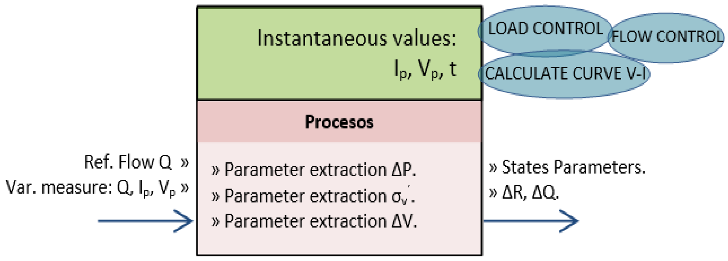
Agent GENERATE STIMULUS
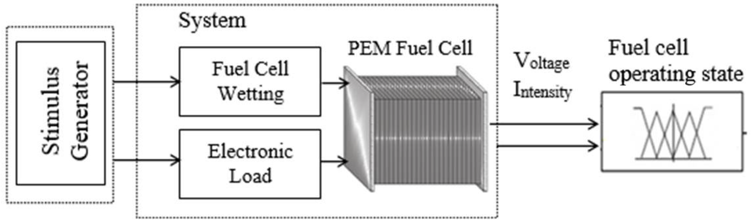
The agent is assigned to the stimuli control tasks {load change (ΔI), flow rate change (ΔQ) and current intensity oscillation frequency (fΔI)} to be applied to the PEMFC. To do so, the agent uses the abilities of the low-level acting agents CONTROL LOAD, CONTROL Q, and CALCULATE V-I CURVE (Figure 13).
Additionally, the GENERATE STIMULUS agent is responsible for extracting relevant parameters observed in the temporal electrical response, voltage (Vp), and current intensity (Ip) of the PEMFC to the applied stimuli, Table 4. The value of these parameters is closely related to the degree of humidification of the membrane and, with it, the state of operation of the PEMFC.
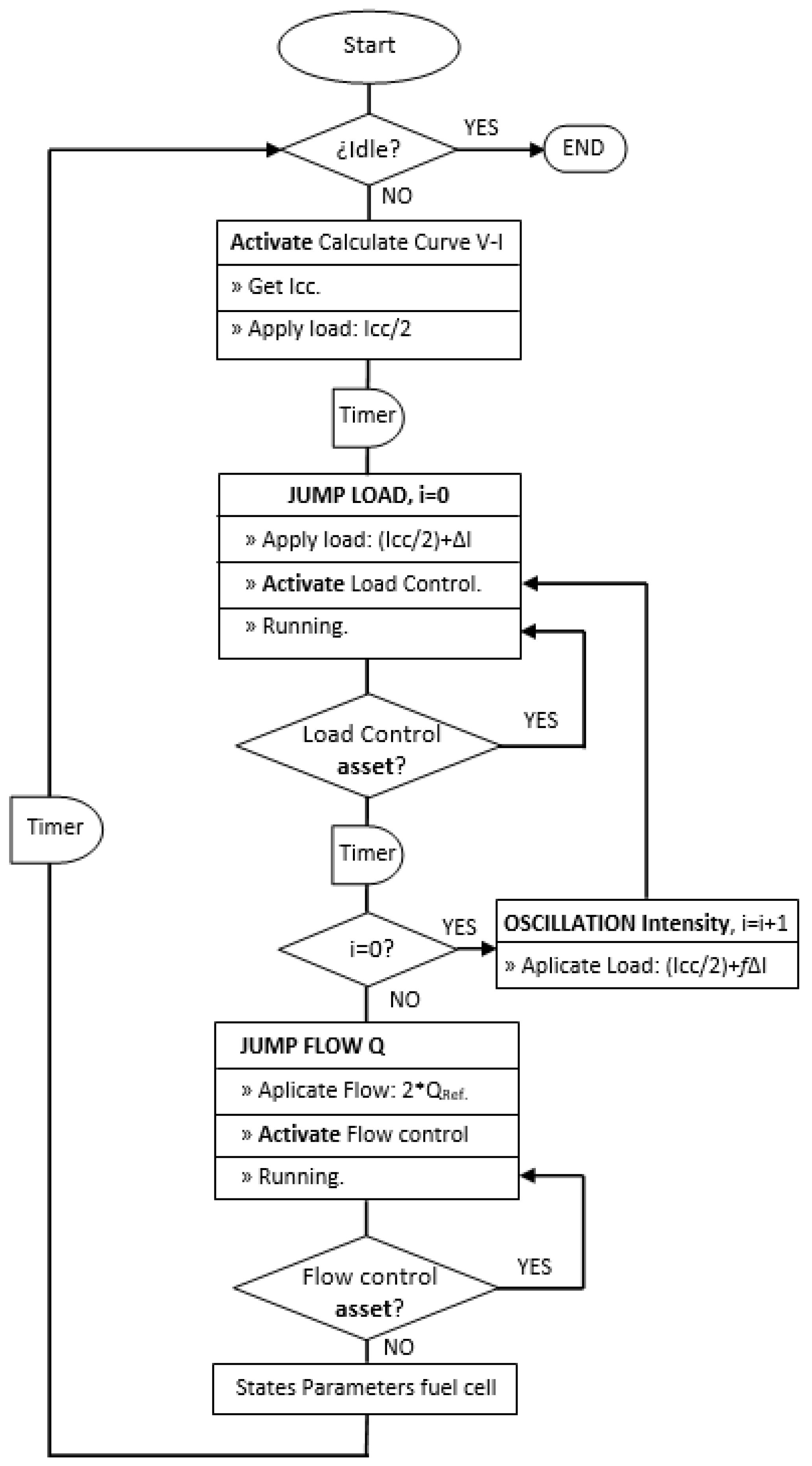
In the agent GENERATE STIMULUS, the values of charge and cathodic flow rate, controlled by low-level acting agents, are applied to the selected point of the polarization curve, whose value is directly related to the short-circuit current, Icc. Thus, the acting agent CALCULATE CURVE V-I is activated to obtain the short-circuit current. The process execution sequence of agent GENERATE STIMULUS is shown in Figure 14.
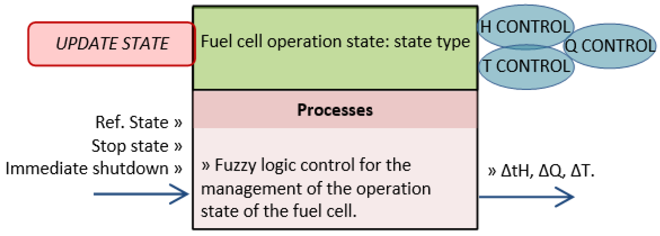
Agent CONTROL STATE
A PEMFC management system must be able to keep its operating away from critical operating states, diverting its trajectory towards the normal operating subspace, for which intelligent perception and control strategies are required to deal with the nonlinearities of the electrical response of the PEMFC. To move from one state of operation to another, it is possible to act on: (1) the humidifying time—the longer it is, the higher the water content in the PEMFC stack; (2) the temperature of the humidifiers—the higher it is, the higher the water content in the PEMFC will also be, if the gas is humidified. The water content will be lower if the gas is not humidified; and (3) the cathode flow rate—the higher it is, the lower the water content in the PEMFC.
In this context, the CONTROL STATE acting agent (Figure 15) has as inputs: the activation signal; the operating state referenced by the OPERATOR; the perception at each instant of the PEMFC stack operating state generated by the UPDATE STATE agent; and the immediate shutdown signal, in case of system failure and shutdown state. The outputs correspond to the “change” values: temperature in the humidifier ΔT, humidifying time of the cathode gas ΔtH, and cathode flow rate ΔQ, values sent to the low-level acting agents of the PEMFC smart management system.
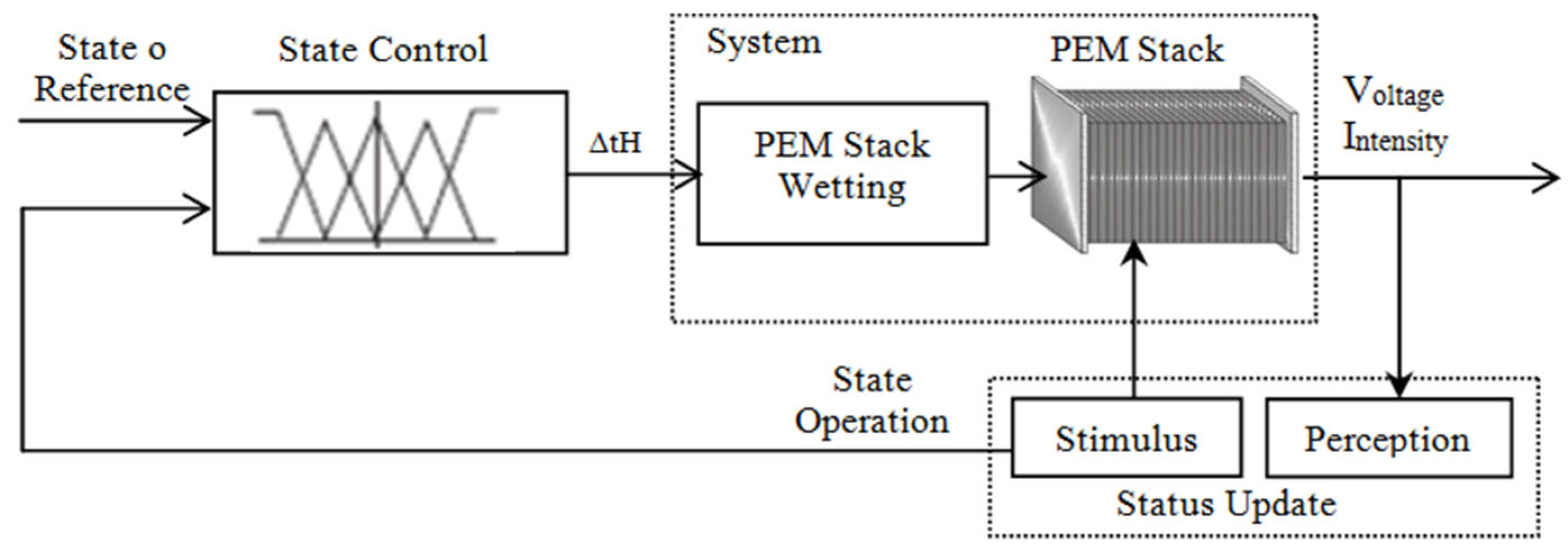
The CONTROL STATE agent proposes a closed-loop control system based on approximate reasoning techniques. Incorporating this controller makes it possible to address the imprecision and uncertainty inherent to the system, directly formulating, in natural language, the control strategies an expert operator would perform, i.e., the control strategy is formulated using a set of IF-THEN rules.
The controller input variables are defined as reference state and operation state, both described by three linguistic terms (fuzzy sets), and defined by trapezoidal membership functions {S (dry), N (normal), and I (flooded)}, which have a direct correspondence to the value of the operating state of the PEMFC. The output variables, change in humidifying time ΔtH and change in cathodic flow rate, are described by three fuzzy sets and also defined by trapezoidal membership functions (Figure 16).
4. Results and Discussion
4.1. Variation of the Membrane Electrical Resistance, Rm
The operating conditions in symmetrical mode of the PEMFC, used for the characterization of the membrane electrical resistance (Rm) using CIS, are shown in Table 5.
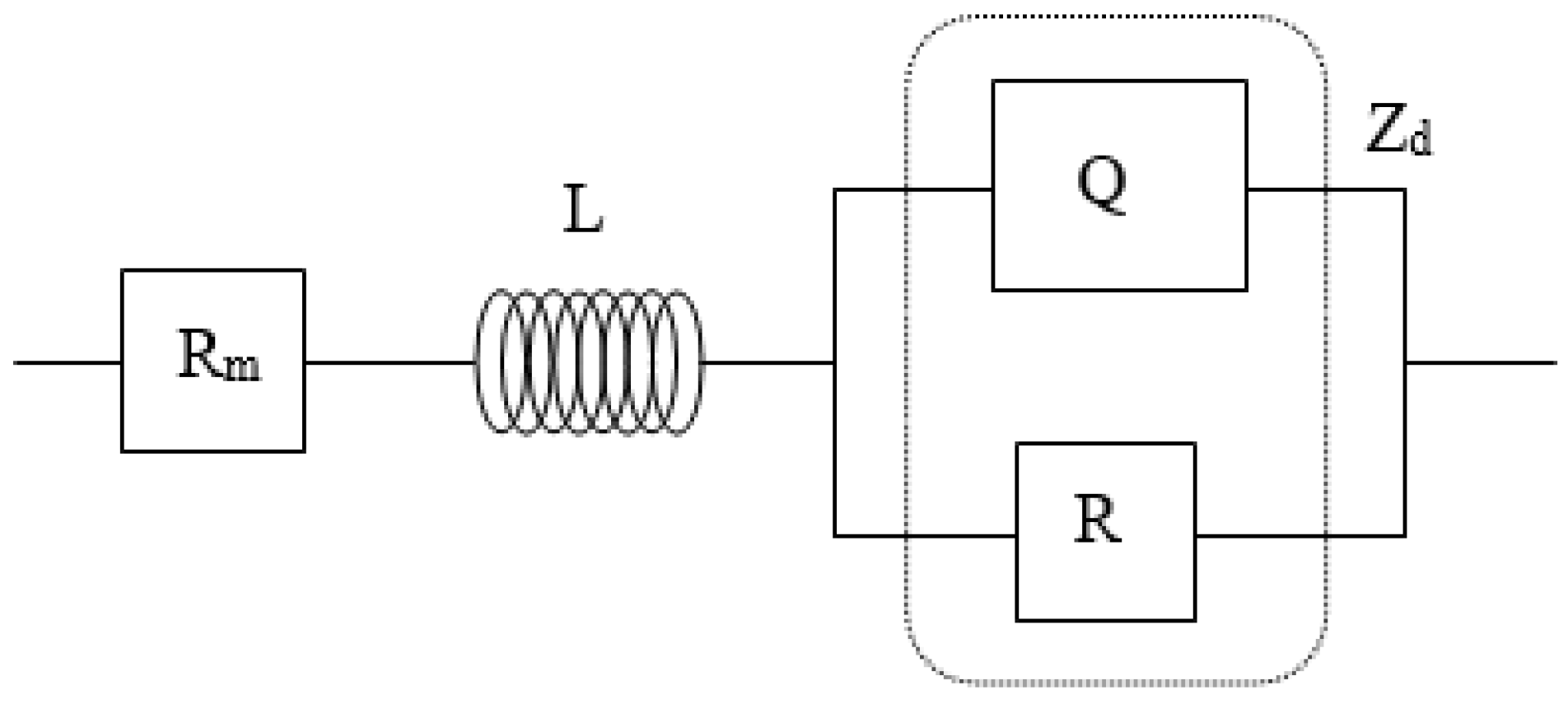
The graphical representation as an equivalent generic electric circuit of the PEMFC, from the experimentally obtained data, is shown in Figure 17. This circuit is interpreted about the physical component or process as follows. Rm: the electrical resistance associated with the proton exchange membrane, in whose behavior the key parameters are the injected gas and its humidity degree, the stack temperature, and especially the water content in the cell. L: the ideal inductance associated with the inductive effects caused by the corrugated collector plates. Zd: the diffuser impedance, formed by a circuit (RQ) of resistance to charge transfer R, in parallel with a pseudocapacitance associated with the electrochemical layer Q.
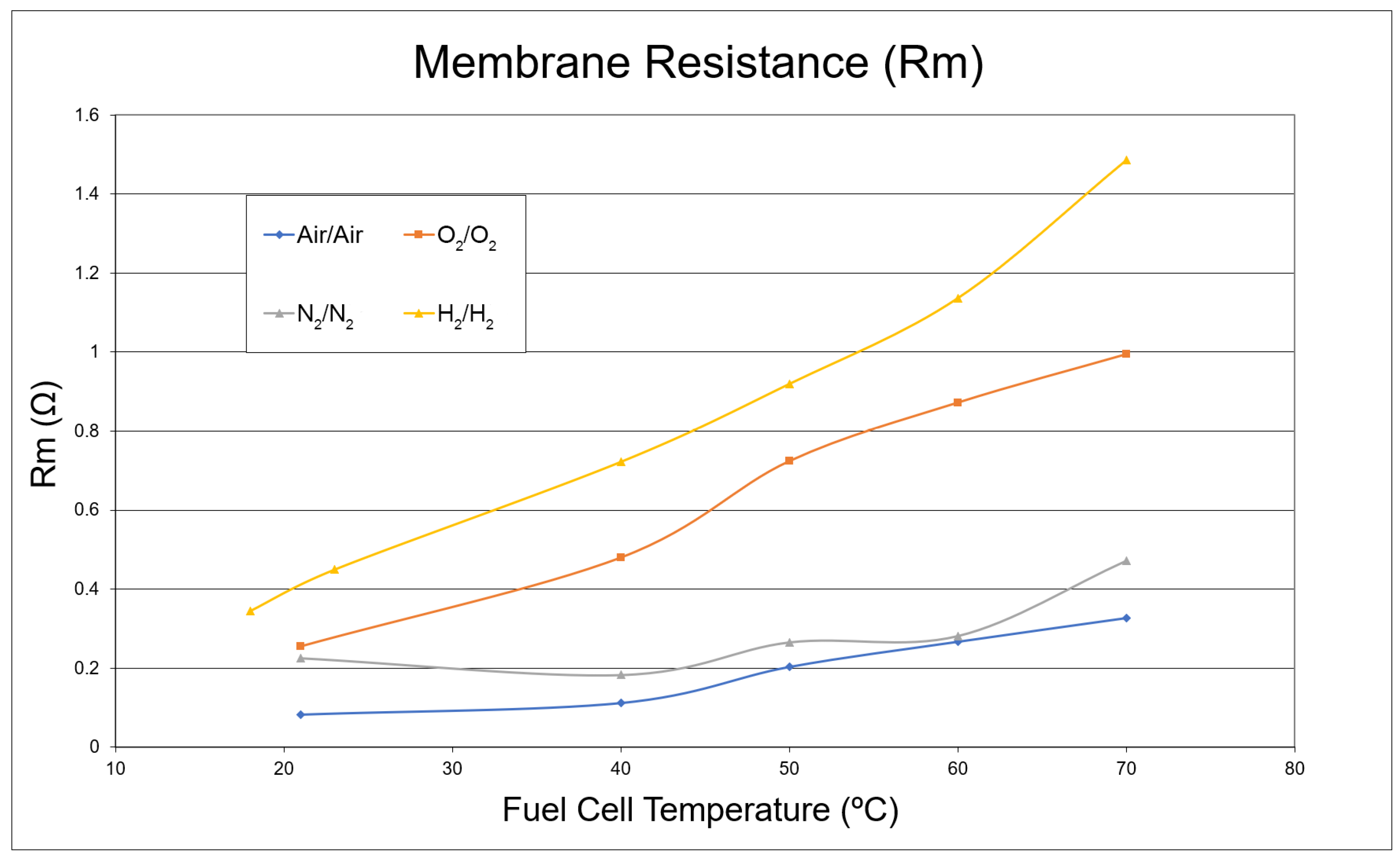
Figure 18 shows the values of Rm in the equivalent electric circuit for different gases injected without humidification and at different PEMFC temperatures. The results show how Rm varies significantly when the injected gases are hydrogen or oxygen, gases with which the cell is adequately coupled. In contrast, they show slight variation for nitrogen and air. In the normal operating temperature range of the PEMFC (40 °C–70 °C), more sensitive variations are observed, and the highest values of Rm are obtained with H2 and O2, decreasing for N2 and air, in this order. These results demonstrate the direct relationship between the resistance of the membrane Rm and the degree of water contained in the membrane, i.e., the higher the temperature, the higher the value of Rm due to the loss of membrane humidity.
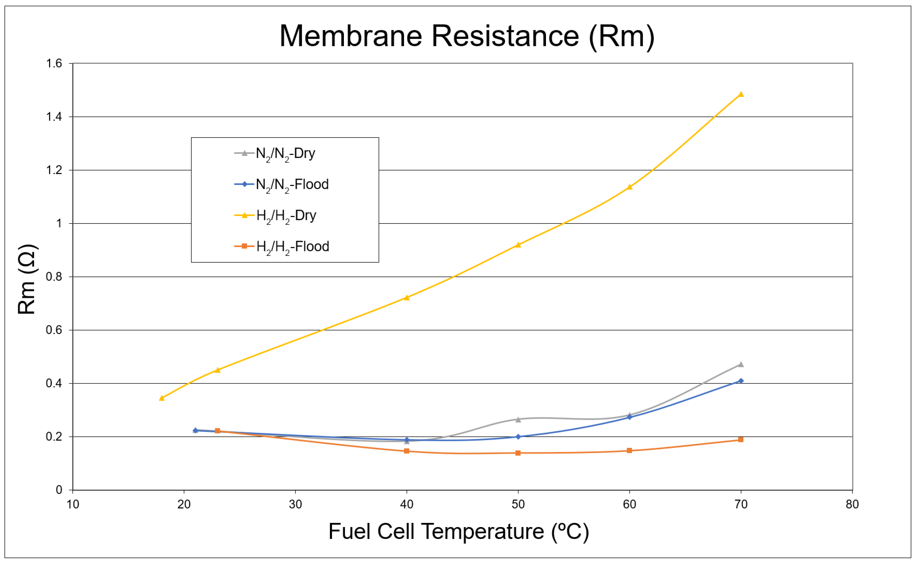
On the other hand, Figure 19 depicts the values of Rm when the gases N2/N2 and H2/H2 are injected, without humifying (dry) and humidified (saturated with water), at different operating temperatures of the PEMFC. The highest values of Rm are observed for the case of dry gases, and are lower for the case of humidified gases. Therefore, we can conclude that, when the injected gas is saturated with water, the value of Rm decreases. This agrees with the fact that the membrane conductivity increases when its water content also increases and, thus, its electrical resistance is lower.
In the normal operating temperature interval of the PEMFC (40 °C–70 °C), increments in the value of Rm are observed, indicating that, when the fuel cell temperature grows, the value of the membrane electrical resistance Rm increases too.
In asymmetrical operating modes, whether with humidified gases or not (as depicted in Figure 18 and Figure 19), the PEMFC is inactive. As a result, the electrochemical half-reactions at the anode (hydrogen oxidation reaction, HOR) and the cathode (oxygen reduction reaction, ORR) do not occur. Under these conditions, no water is produced at the cathode, and there is no migration of protons through the membrane from the anode to the cathode, which would typically carry water molecules with them (known as electroosmotic drag). Additionally, there is no diffusion of water from the cathode to the anode. In this situation, an increase in the temperature of the cell causes a decrease in water content in the membrane and, consequently, its resistance to ion transport increases too.
These patterns can be seen in the results of the CIS and, considering the objective of autonomous operation under optimal humidification conditions, it is proposed that the identification in real time of the operating state of the PEMFC stack stem from the changes identified in the electrical resistance of the membrane Rm.
4.2. Operating State Detection of the PEMFC
Multiple experimental sessions were conducted, leading the PEMFC to work in its three initially defined operating states, dry, normal, and flooded, aiming to validate the methods to obtain the “state parameters” and adjust the limits of the fuzzy number labels.
The first state serves as a starting point where the fuel cell operates stably, while the last two states correspond to critical zones where the cell can suffer irreversible damage. Hence, there is an interest in always keeping the cell operating away from these critical zones, which results in a good electrical response. The basic difference between these three states lies in the water content in the cell membrane, which leads to shifts in the V-I curve.
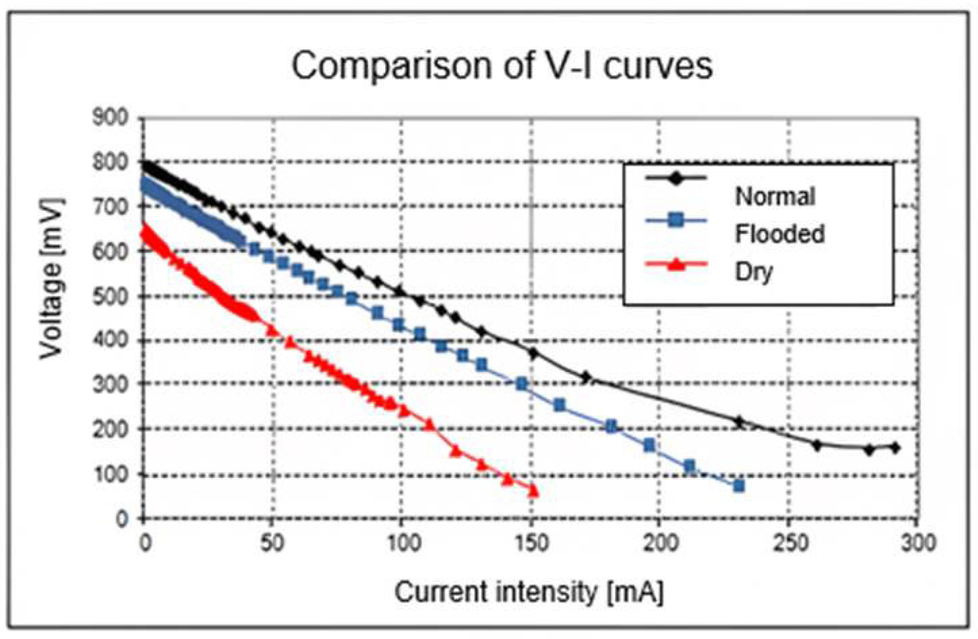
Thus, the operational state referred to as “NORMAL” is described by its electrical response behavior when the cell operates under standard conditions, where issues related to membrane resistance and diffusion at high currents are minimal. However, if the cell is in the “DRY” state, sharp deviations of the overpotential in the ohmic region are observed, resembling the response depicted in Figure 20. Finally, diffusion problems at high currents are further amplified when the cell is in the “FLOODED” state, resulting in a V-I curve behavior similar to that presented in Figure 20, [52].
The standard operating conditions established in [52] determine the NORMAL state, while the conditions of the DRY and FLOODED states have been intentionally induced to make the stack operate with low and high water content in the membrane, respectively. Figure 20 shows three voltage–current intensity characteristic curves of the PEMFC, which correspond to its three operating states. The so-called critical states are “Dry and Flooded”, and their electrical responses present values lower than the state considered “Normal”. This confirms the need to move the operating point of the fuel cell towards the subspaces with the best electrical performance, a task to be performed by the CONTROL STATE agent.
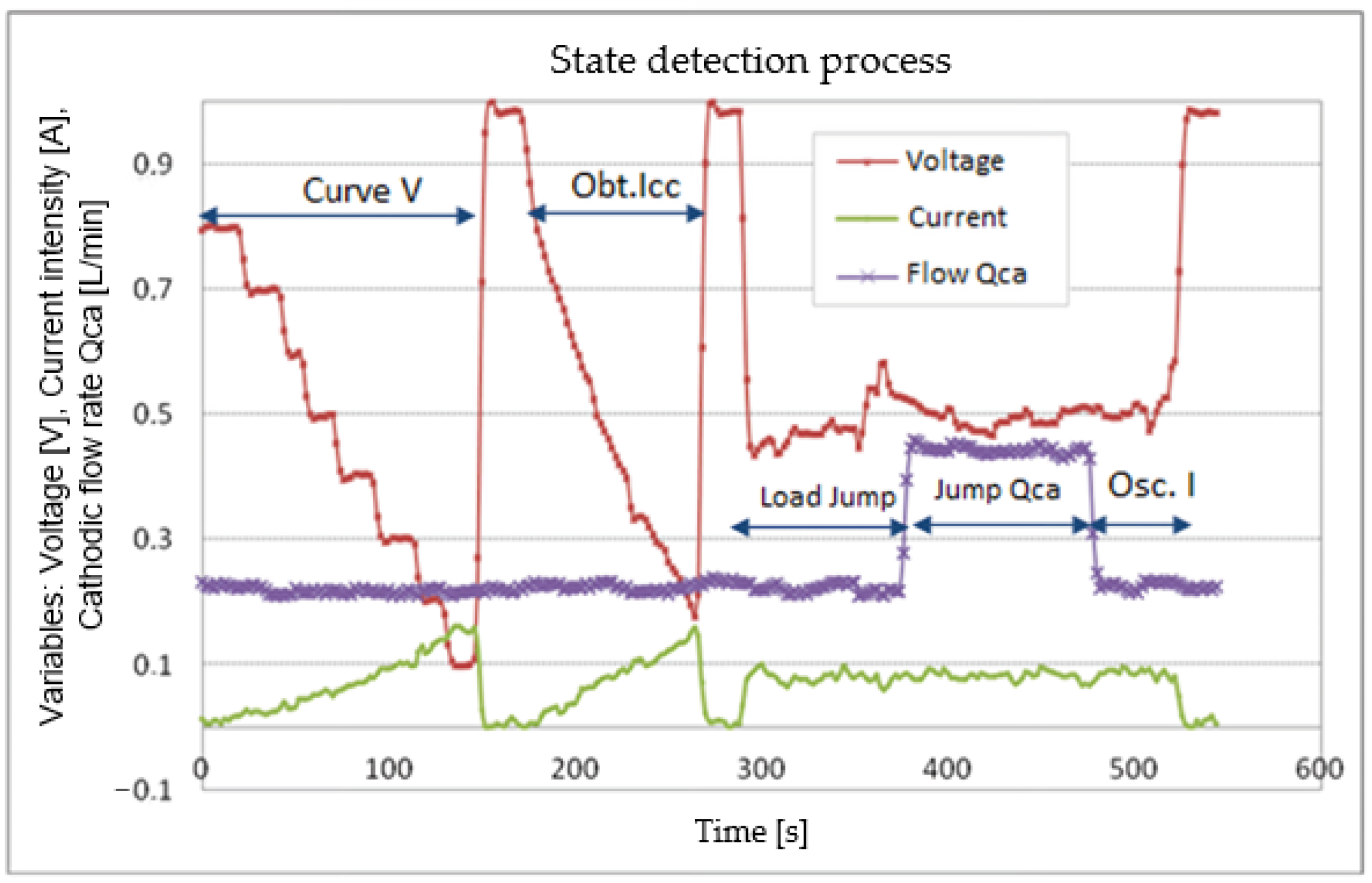
The temporal evolution of the variables measured during one of the experiments carried out in the execution of the UPDATE STATE perceiving agent is shown in Figure 21. It is easy to discern the activation of the GENERATE STIMULUS acting agent. In this sense, if there is no active fault, the required acting agents are activated to first obtain the value of the short-circuit current, Icc (Obt.Icc), the value needed, then, to apply the three stimuli to the PEMFC: load jump, cathode flow rate jump (Qca), and current intensity oscillations (Osc. I).
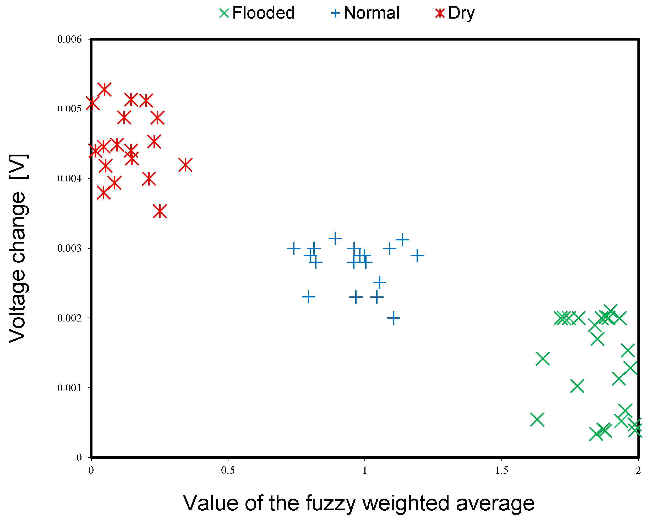
The reproducibility of the experimental results of the value of the fuzzy weighted average NB generated by the UPDATE STATE perceiving agent from the state parameters in the three operating states of the PEMFC is shown in the abscissa of Figure 22. At first glance, differences can be identified in the three operating states of the PEMFC between the different experiments, which confirms that the state estimator through the value of the fuzzy weighted average seems to be the best, considering the information of the three state parameters, unlike the fuzzy tree state estimator that considers two parameters [6] and presents a very small range of values in the three states of operation of the PEMFC. This confirms the potential use of fuzzy weighted average techniques for the estimation of the operating state of the PEMFC. On the other hand, the ordinate of Figure 22 shows the value of the voltage change parameter, whose value presents very low ranges in the three operating states of the PEMFC and great overlap among them. Hence, this parameter is considered to have a lower level of reliability in obtaining the fuzzy weighted average.
4.3. Control of the PEMFC Normal State
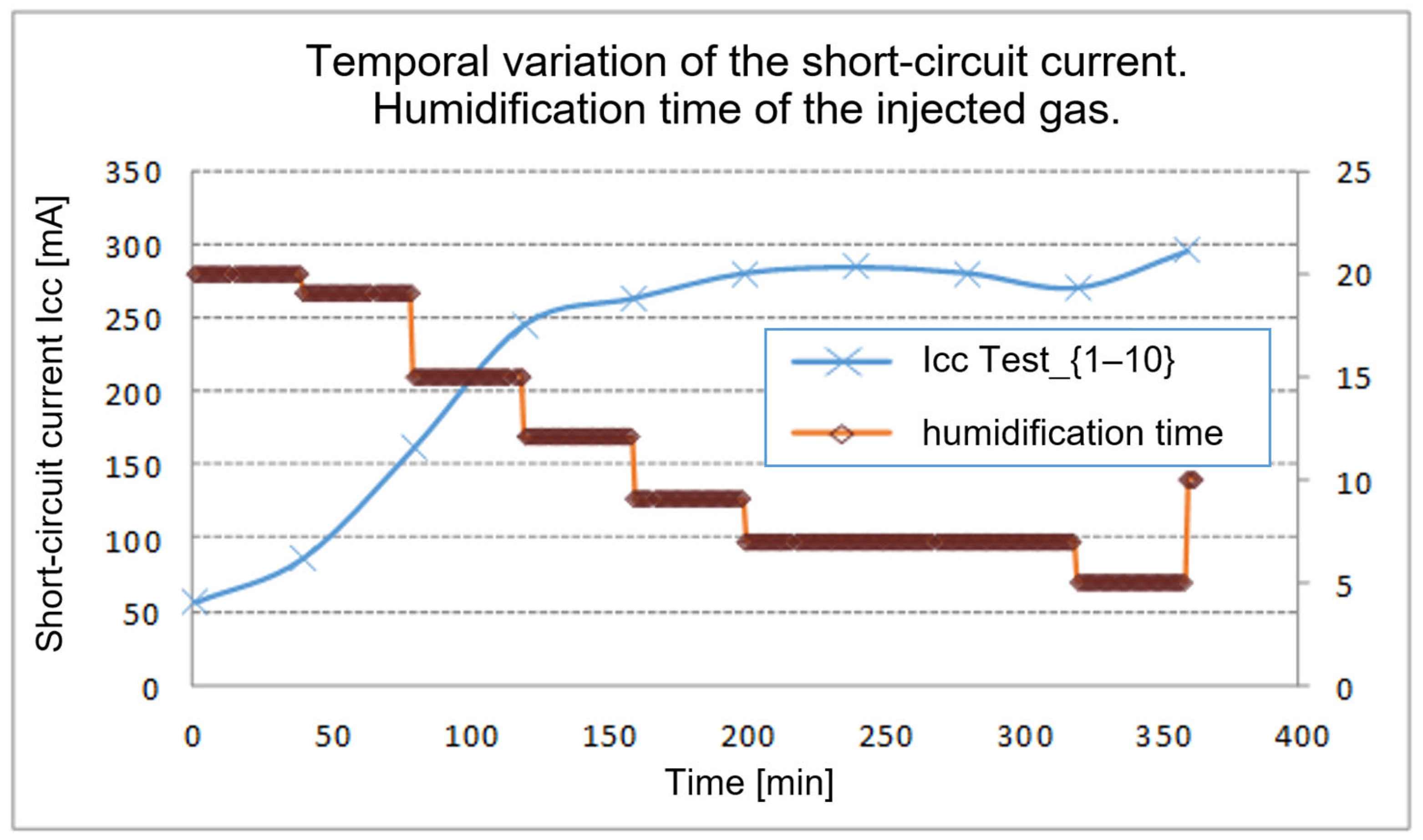
Based on the current state of operation of the PEMFC generated by the UPDATE STATE perceptive agent, the CONTROL STATE acting agent proceeds to execute the proper control action based on rules to determine the value of the action to perform, either in the humidifying time or in the flow rate of the gas injected into the fuel cell. Figure 23 shows the change in the PEMFC short-circuit current, Icc, over time—the blue curve, obtained in each execution cycle of the CONTROL STATE agent. It starts in the dry state (Test-1), where the low performance of the PEMFC is displayed, the short-circuit current supplied under these conditions being equal to 60 mA.
As 100% humidified gas flow is introduced into the cathode; with a maximum humidification time, an improvement is observed in the electrical response of the PEMFC stack, with a short-circuit current value of 85 mA (Test-2). Once the stack reaches optimal humidification conditions, the short-circuit current values between the consecutive tests are very close. This improvement in the electrical response confirms that the operating point of the PEMFC diverts away from the dry state, the starting state, Test-1, towards the normal state, Test-7. A negative slope is also seen in the “humification time” variable in Figure 23 (red curve), starting at the opening time of the valve with a maximum value of the 20 s. This confirms that, for the PEMFC stack, the humidification period shortens as the humidity degree increases, given that gas with lower relative humidity is injected. Test-9 presents a decrement in the value of the short-circuit current, which indicates that the operating point of the PEMFC tends toward the flooded state, under which conditions the controller increases the cathodic flow rate together with the opening time of the valve to take the operating point of the fuel cell stack to the normal state.
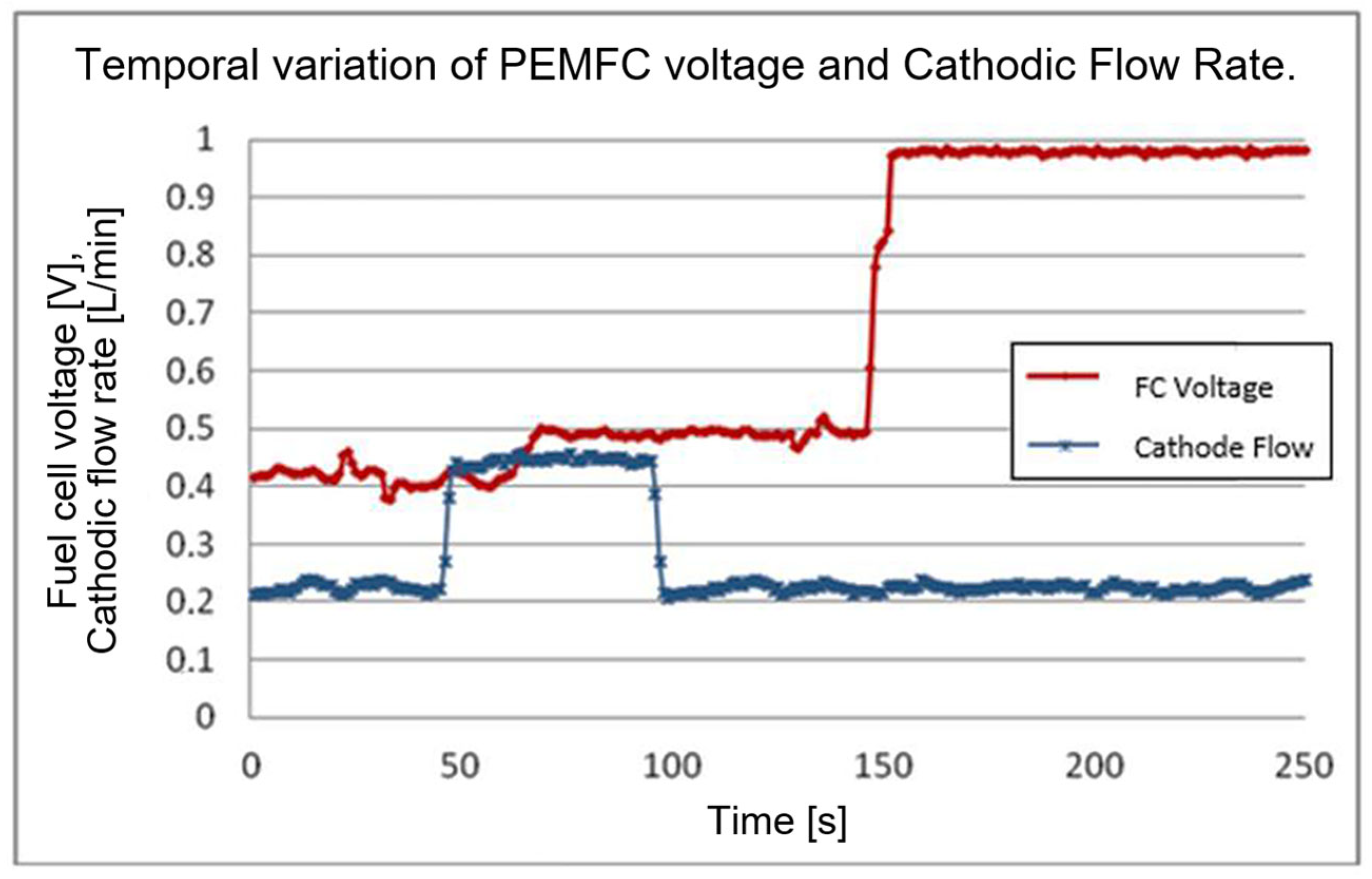
The temporal evolution of the voltage generated by the PEMFC stack is depicted in Figure 24. The clear recovery of the electrical response after applying the change in the cathodic flow rate confirms the water entrainment in the PEMFC, after which the flow rate returns to the reference value. However, the voltage (0.5 Vdc) of the PEMFC is maintained, indicating its good operating state. Finally, the PEMFC voltage returns to open-circuit values, confirming the end of the execution of the CONTROL STATE agent tests.
5. Conclusions
Control based on intelligent agents of perception and control comprises a hierarchy of layers with varying degrees of abstraction and time windows. Within these agents, different techniques and control models are integrated, including classic direct control, qualitative control based on expert knowledge, and supervisory control by a human operator. More complex perception and decision strategies are required to deal with the non-linearities of the electrical response of the PEMFC.
The CONTROL STATE agent ensures the operation of the PEMFC stack outside the critical operating zones (flooded and dry states), by incorporating a fuzzy controller that allows us to handle the imprecision and uncertainty inherent to the system by formulating control strategies directly in natural language. These strategies regulate the humidification time and the flow rate in the PEMFC.
The UPDATE STATE perceiving agent integrates stimuli-response techniques and an approximate reasoning model. This integration guarantees the real-time characterization of the critical states of the PEMFC, depending on the humidity level of the membrane.
Finally, the hierarchical model based on intelligent agents has been experimentally validated with a PEMFC stack under various working conditions and scenarios focused, as an example, on managing the hybrid phenomena specific to the fuel cell.
Author Contributions
Conceptualization, A.R. and W.A.; writing—original draft preparation, A.R. and W.A.; writing—review and editing, A.R., L.G. and J.A.-C. All authors have read and agreed to the published version of the manuscript.
Funding
This research received no external funding.
Data Availability Statement
The data presented in this study are available upon request to the corresponding author.
Acknowledgments
The authors thank the group of Advanced Control of Energy Systems (Control Avanzado de Sistemas de Energía CASE-CIDIS) of ESPOL (Escuela Superior Politécnica del Litoral), the National Hydrogen and Fuel Cell Technology Testing Centre (Centro Nacional del Hidrógeno de España CNH2), and the Centre for Automation and Robotics (CAR-CSIC).
Conflicts of Interest
The authors declare no conflict of interest. The funders had no role in the design of the study; in the collection, analyses, or interpretation of data; in the writing of the manuscript; or in the decision to publish the results.
References
- Rubio, A.; Agila, W. Sustainable Energy: A Strategic Overview of Fuel Cells. In Proceedings of the 2019 8th International Conference on Renewable Energy Research and Applications (ICRERA), Brasov, Romania, 3–6 November 2019; pp. 239–243. [Google Scholar]
- Rubio, A.; Agila, W. A Novel System-Level Model for a Fuel Cell in a Strategic Context. In Proceedings of the 2018 7th International Conference on Renewable Energy Research and Applications (ICRERA), Paris, France, 14–17 October 2018; pp. 1044–1048. [Google Scholar]
- Munjewar, S.S.; Thombre, S.B.; Mallick, R.K. A comprehensive review on recent material development of passive direct methanol fuel cell. Ionics 2017, 23, 1–18. [Google Scholar] [CrossRef]
- Lin-Kwong-Chon, C.; Grondin-Pérez, B.; Kadjo, J.J.A.; Damour, C.; Benne, M. A review of adaptive neural control applied to proton exchange membrane fuel cell systems. Annu. Rev. Control 2019, 47, 133–154. [Google Scholar] [CrossRef]
- Yang, B.; Li, J.; Li, Y.; Guo, Z.; Zeng, K.; Shu, H.; Cao, P.; Ren, Y. A critical survey of proton exchange membrane fuel cell system control: Summaries, advances, and perspectives. Int. J. Hydrogen Energy 2022, 47, 9986–10020. [Google Scholar] [CrossRef]
- Rubio, G.A.; Agila, W.E. A Fuzzy Model to Manage Water in Polymer Electrolyte Membrane Fuel Cells. Processes 2021, 9, 904. [Google Scholar] [CrossRef]
- Rubio, A.; Agila, W.; Miranda, L.; Lima, B. Real-Time Qualitative Model for Estimate Water Content in PEM Fuel Cell. In Proceedings of the 2019 8th International Conference on Renewable Energy Research and Applications (ICRERA), Brasov, Romania, 3–6 November 2019; pp. 455–459. [Google Scholar]
- Rubio, A.; Agila, W. Dynamic Model of Proton Exchange Membrane Fuel Cells: A Critical Review and a Novel Model. In Proceedings of the IEEE, International Conference on Renewable Energy Research and Applications (ICRERA), Brasov, Rumania, 3–6 November 2019; pp. 353–358. [Google Scholar]
- Chavan, S.L.; Talange, D.B. Modeling and performance evaluation of PEM fuel cell by controlling its input parameters. Energy 2017, 138, 437–445. [Google Scholar] [CrossRef]
- Gomathi, K.; Karthik, M.; Usha, S. An intelligent parametric modeling and identification of a 5 kW ballard PEM fuel cell system based on dynamic recurrent networks with delayed context units. Int. J. Hydrogen Energy 2021, 46, 15912–15927. [Google Scholar]
- He, K.; Zhang, C.; He, Q.; Wu, Q.; Jackson, L.; Mao, L. Effectiveness of PEMFC historical state and operating mode in PEMFC prognosis. Int. J. Hydrogen Energy 2020, 45, 32355–32366. [Google Scholar] [CrossRef]
- Li, J.; Yu, T. Sensors integrated control of PEMFC gas supply system based on large-scale deep reinforcement learning. Sensors 2021, 21, 349. [Google Scholar] [CrossRef]
- Feng, Z.; Huang, J.; Jin, S.; Wang, G.; Chen, Y. Artificial intelligence-based multi-objective optimisation for proton exchange membrane fuel cell: A literature review. J. Power Sources 2022, 520, 230808. [Google Scholar] [CrossRef]
- Yang, B.; Li, D.; Zeng, C.; Chen, Y.; Guo, Z.; Wang, J.; Shu, H.; Yu, T.; Zhu, J. Parameter extraction of PEMFC via Bayesian regularization neural network based meta-heuristic algorithms. Energy 2021, 228, 120592. [Google Scholar] [CrossRef]
- Li, J.; Yu, T. A new adaptive controller based on distributed deep reinforcement learning for PEMFC air supply system. Energy Rep. 2021, 7, 1267–1279. [Google Scholar] [CrossRef]
- Arzaghi, H.; Sedighizadeh, M. A neuro adaptive control strategy for movable power source of proton exchange membrane fuel cell using wavelets. In Proceedings of the International Universities Power Engineering Conference (IUPEC) 2007, Newcastle upon Tyne, UK, 6–8 September 2006; pp. 545–549. [Google Scholar] [CrossRef]
- Zhao, D.; Li, F.; Ma, R.; Zhao, G.; Huangfu, Y. An unknown input nonlinear observer based fractional order PID control of fuel cell air supply system. IEEE Trans. Ind. Appl. 2020, 56, 5523–5532. [Google Scholar] [CrossRef]
- AbouOmar, M.; Zhang, H.; Su, Y.X. Fractional Order Fuzzy PID Control of Automotive PEM Fuel Cell Air Feed System Using Neural Network Optimization Algorithm. Energies 2019, 12, 1435. [Google Scholar] [CrossRef] [Green Version]
- Deng, H.; Li, Q.; Cui, Y.; Zhu, Y.; Chen, W. Nonlinear controller design based on cascade adaptive sliding mode control for PEM fuel cell air supply systems. Int. J. Hydrogen Energy 2019, 44, 19357–19369. [Google Scholar] [CrossRef]
- Zhang, H.; Wang, Y.; Wang, D.; Wang, Y. Adaptive robust control of oxygen excess ratio for PEMFC system based on type-2 fuzzy logic system. Inf. Sci. 2019, 511, 1–17. [Google Scholar] [CrossRef]
- Han, J.; Yu, S.; Yi, S. Oxygen excess ratio control for proton exchange membrane fuel cell using model reference adaptive control. Int. J. Hydrogen Energy 2019, 44, 18425–18437. [Google Scholar] [CrossRef]
- Han, J.; Yu, S.; Yi, S. Adaptive control for robust air flow management in an automotive fuel cell system. Appl. Energy 2017, 190, 73–83. [Google Scholar] [CrossRef]
- Sun, L.; Shen, J.; Hua, Q.; Lee, K.Y. Data-driven oxygen excess ratio control for proton exchange membrane fuel cell. Appl. Energy 2018, 231, 866–875. [Google Scholar] [CrossRef]
- Mammar, K.; Laribi, S. Application of adaptive neuro-fuzzy inference system techniques to predict water activity in proton exchange membrane fuel cell. J. Electrochem. Energy Convers. Storage 2018, 15, 041009. [Google Scholar] [CrossRef]
- Benchouia, N.E.; Derghal, A.; Mahmah, B.; Madi, B.; Khochemane, L.; Aoul, E.H. An adaptive fuzzy logic controller (AFLC) for PEMFC fuel cell. Int. J. Hydrogen Energy 2015, 40, 13806–13819. [Google Scholar] [CrossRef]
- Rigatos, G.; Siano, P.; Wira, P.; Liu, J. A Nonlinear H-Infinity Approach to Optimal Control of PEM Fuel Cells. Intell. Ind. Syst. 2017, 3, 43–58. [Google Scholar] [CrossRef]
- Hammoudi, M.Y.; Kraa, O.; Saadi, R.; Ayad, M.Y.; Bacha, S.; Boukhlouf, A. Nonlinear Control of a Fuel Cell Interleaved Boost Converter Using Weighted Mixed Sensitivity H∞. In Proceedings of the 2018 International Conference on Electrical Sciences and Technologies in Maghreb (CISTEM), Algiers, Algeria, 28–31 October 2018; pp. 1–5. [Google Scholar]
- Afsharinejad, A.; Asemani, M.H.; Dehghani, M. Optimal linear parameter varying controller design for proton exchange membrane fuel cell using LMI techniques. In Proceedings of the 2020 28th Iranian Conference on Electrical Engineering (ICEE), Tabriz, Iran, 4–6 August 2020; pp. 1–5. [Google Scholar]
- Abbaker, A.M.; Wang, H.O.; Tian, Y. Adaptive integral type-terminal sliding mode control for PEMFC air supply system using time delay estimation algorithm. Asian J. Control 2022, 24, 217–226. [Google Scholar] [CrossRef]
- Javaid, U.; Mehmood, A.; Arshad, A.; Imtiaz, F.; Iqbal, J. Operational efficiency improvement of PEM fuel cell—A sliding mode based modern control approach. IEEE Access 2020, 8, 95823–95831. [Google Scholar] [CrossRef]
- Yin, X.; Wang, X.; Wang, L.; Qin, B.; Liu, H.; Jia, L.; Cai, W. Cooperative control of air and fuel feeding for PEM fuel cell with ejector-driven recirculation. Appl. Therm. Eng. 2021, 199, 117590. [Google Scholar] [CrossRef]
- Souissi, A. Adaptive sliding mode control of a PEM fuel cell system based on the super twisting algorithm. Energy Rep. 2021, 7, 3390–3399. [Google Scholar] [CrossRef]
- Li, Y.; Pei, P.; Ma, Z.; Ren, P.; Huang, H. Method for system parameter identification and controller parameter tuning for super-twisting sliding mode control in proton exchange membrane fuel cell system. Energy Convers. Manag. 2021, 243, 114370. [Google Scholar] [CrossRef]
- Legala, A.; Zhao, J.; Li, X. Machine learning modeling for proton exchange membrane fuel cell performance. Energy AI 2022, 10, 100183. [Google Scholar] [CrossRef]
- Li, J.; Li, Y.; Yu, T. Temperature Control of Proton Exchange Membrane Fuel Cell Based on Machine Learning. Front. Energy Res. 2021, 9, 582. [Google Scholar] [CrossRef]
- Cao, Y.; Li, Y.; Zhang, G.; Jermsittiparsert, K.; Nasseri, M. An efficient terminal voltage control for PEMFC based on an improved version of whale optimization algorithm. Energy Rep. 2020, 6, 530–542. [Google Scholar] [CrossRef]
- Yang, B.; Zeng, C.; Wang, L.; Guo, Y.; Chen, G.; Guo, Z.; Chen, Y.; Li, D.; Cao, P.; Shu, H.; et al. Parameter identification of proton exchange membrane fuel cell via Levenberg-Marquardt backpropagation algorithm. Int. J. Hydrogen Energy 2021, 46, 22998–23012. [Google Scholar] [CrossRef]
- Lu, X.; Kanghong, D.; Guo, L.; Wang, P.; Yildizbasi, A. Optimal estimation of the Proton Exchange Membrane Fuel Cell model parameters based on extended version of Crow Search Algorithm. J. Clean. Prod. 2020, 272, 122640. [Google Scholar] [CrossRef]
- Bao, S.; Ebadi, A.; Toughani, M.; Dalle, J.; Maseleno, A.; Yıldızbası, A. A new method for optimal parameters identification of a PEMFC using an improved version of Monarch Butterfly Optimization Algorithm. Int. J. Hydrogen Energy 2020, 45, 17882–17892. [Google Scholar] [CrossRef]
- Hachana, O.; El-Fergany, A.A. Efficient PEM fuel cells parameters identification using hybrid artificial bee colony differential evolution optimizer. Energy 2022, 250, 123830. [Google Scholar] [CrossRef]
- Abaza, A.; El-Sehiemy, R.A.; Mahmoud, K.; Lehtonen, M.; Darwish, M. Optimal estimation of proton exchange membrane fuel cells parameter based on coyote optimization algorithm. Appl. Sci. 2021, 11, 2052. [Google Scholar] [CrossRef]
- Nagulapati, V.M.; Kumar, S.S.; Annadurai, V.; Lim, H. Machine learning based fault detection and state of health estimation of proton exchange membrane fuel cells. Energy AI 2023, 12, 100237. [Google Scholar] [CrossRef]
- Yuan, X.; Chen, F.; Xia, Z.; Zhuang, L.; Jiao, K.; Peng, Z.; Wang, B.; Bucknall, R.; Yearwood, K.; Hou, Z. A Novel Feature Susceptibility Approach for a PEMFC Control System based on an Improved XGBoost-Boruta Algorithm. Energy AI 2023, 12, 100229. [Google Scholar] [CrossRef]
- Ding, R.; Zhang, S.; Chen, Y.; Rui, Z.; Hua, K.; Wu, Y.; Li, X.; Duan, X.; Wang, X.; Li, J.; et al. Application of Machine Learning in Optimizing Proton Exchange Membrane Fuel Cells: A Review. Energy AI 2022, 9, 100170. [Google Scholar] [CrossRef]
- Barbir, F. PEM Fuel Cells: Theory and Practice; Academic Press: Cambridge, MA, USA, 2012; Chapter 2; ISBN 0123877105; 9780123877109. [Google Scholar]
- Sanaguano, D.; Agila, W.; Rubio, G. Open Control Architecture for the Characterization and Control of the PEM Fuel Cell. In Proceedings of the IEEE Fourth Ecuador Technical Chapters Meeting (ETCM), Guayaquil, Ecuador, 11–15 November 2019. [Google Scholar] [CrossRef]
- Equipamientos de Ensayo de Pilas de Combustible de Hydrogenics. Hydrogenics. Available online: http://www.hydrogenics.com/test/ (accessed on 15 August 2019).
- “Testing Equipment” de fuelcell.com, Perteneciente a Electrochem. Available online: http://fuelcell.com/index.asp?PageAction=VIEWCATS&Category=20 (accessed on 15 August 2019).
- Hombrados, A.; González, L.; Rubio, M.; Agila, W.; Guinea, D.; Chinarro, E.; Moreno, B.; Jurado, J. Symmetrical electrode mode for PEMFC characterization by impedance spectroscopy. J. Power Sources 2005, 151, 25–31. [Google Scholar] [CrossRef]
- Tang, Z.; Huang, Q.-A.; Wang, Y.-J.; Zhang, F.; Li, W.; Li, A.; Zhang, L.; Zhang, J. Recent progress in the use of electrochemical impedance spectroscopy for the measurement, monitoring, diagnosis and optimization of proton exchange membrane fuel cell performance. J. Power Sources 2020, 468, 228361. [Google Scholar] [CrossRef]
- Atlam, Ö.; Dündar, G. A practical equivalent electrical circuit model for proton exchange membrane fuel cell (PEMFC) systems. Int. J. Hydrogen Energy 2021, 46, 13230–13239. [Google Scholar] [CrossRef]
- O’Hayre, R.; Cha, S.W.; Colella, W.; Prinz, F.B. Fuel Cell Fundamentals; John Wiley & Son: New York, NY, USA, 2006; ISBN 13 978-0-471-74148-0. [Google Scholar]
Figure 1.
The layout of the PEMFC.

Figure 2.
Components of the upper section of the PEM fuel cell.

Figure 3.
Final assembly of the PEM fuel cell stack.

Figure 4.
Integrated measurement and control system for state variables of PEM fuel cell stacks with a maximum power output of 500 [W].
Figure 4.
Integrated measurement and control system for state variables of PEM fuel cell stacks with a maximum power output of 500 [W].

Figure 5.
Gas humidity and temperature regulation system.

Figure 6.
Diagram of the perception and control system of the operating state of the PEMFC.

Figure 7.
Perceiving and acting intelligent agents, variables in shared memory, and resolution time per level.
Figure 7.
Perceiving and acting intelligent agents, variables in shared memory, and resolution time per level.

Figure 8.
Agent PERCEIVE ALERT.

Figure 9.
Information flowchart of the agent PERCEIVE ALERT.

Figure 10.
Agent UPDATE STATE.

Figure 11.
Block diagram of the processes in the UPDATE STATE agent.

Figure 12.
Fuzzy set of the variable state type.

Figure 13.
Acting agent GENERATE STIMULUS.

Figure 14.
The process execution sequence of agent GENERATE STIMULUS.

Figure 15.
Agent CONTROL STATE.

Figure 16.
The process scheme of the agent CONTROL STATE.

Figure 17.
Generic equivalent electric circuit of the PEMFC stack.

Figure 18.
Variation of Rm as a function of the non-humidified gas at different temperatures of the PEMFC.
Figure 18.
Variation of Rm as a function of the non-humidified gas at different temperatures of the PEMFC.

Figure 19.
Variation of Rm for two humidification degrees of the gases.

Figure 20.
Experimental data of the V-I curve for the three operating states of the PEMFC.

Figure 21.
Temporal evolution of the flow rate and the electric variables of the PEMFC stack during the stimulation and state detection process.
Figure 21.
Temporal evolution of the flow rate and the electric variables of the PEMFC stack during the stimulation and state detection process.

Figure 22.
State Parameters of the PEMFC, output of the GENERATE STIMULUS agent.

Figure 23.
Temporal variation of the short-circuit current, Icc, during the execution of the CONTROL STATE agent.
Figure 23.
Temporal variation of the short-circuit current, Icc, during the execution of the CONTROL STATE agent.

Figure 24.
Temporal variation of the voltage generated by the PEMFC during changes in the cathodic flow rate.
Figure 24.
Temporal variation of the voltage generated by the PEMFC during changes in the cathodic flow rate.

Table 2.
Thickness and dimensions of the components of the PEM fuel cell.
| Components | Thickness (mm) | Surface Area (cm × cm) |
|---|---|---|
| Teflon gaskets and thin seals | 1.4 | 7 × 7 |
| Passive-aluminum corrugated bipolar plate | 1.0 | 5 × 5 |
| Electrode | 0.35 | 5 × 5 |
| Nafion-112 membrane | 0.127 | 6 × 6 |
| Electrode | 0.35 | 5 × 5 |
| Passive-aluminum corrugated bipolar plate | 1.0 | 5 × 5 |
| Teflon gaskets and thin seals | 1.4 | 7 × 7 |
Table 3.
Alert estimating functions.
| Alert Type | Failure | Conditions |
|---|---|---|
| 1 | Sensor | |
| 2 | Threshold | |
| 3 | Reference | |
| 4 | Emergency stop |
Table 4.
Stimuli and extracted parameters.
| Applied Stimulus | Extracted Parameter |
|---|---|
| Electrical current change, ΔI | Slope change, ΔP |
| Flow rate change, ΔQ | Voltage amplitude, |
| Current intensity oscillation frequency, fΔI | Voltage change, ΔV |
Table 5.
Operating conditions of the PEMFC in symmetrical mode.
| Gas Used | Cathode (L/min) | Anode (L/min) | Pressure (bar) | Tstack (°C) |
|---|---|---|---|---|
| Air/air | 0.25 | 0.15 | 0.5 | 40, 50, 60, 70 |
| N2/N2 | 0.25 | 0.15 | 0.5 | 40, 50, 60, 70 |
| O2/O2 | 0.25 | 0.15 | 0.5 | 40, 50, 60, 70 |
| H2/H2 | 0.25 | 0.15 | 0.5 | 40, 50, 60, 70 |
Disclaimer/Publisher’s Note: The statements, opinions and data contained in all publications are solely those of the individual author(s) and contributor(s) and not of MDPI and/or the editor(s). MDPI and/or the editor(s) disclaim responsibility for any injury to people or property resulting from any ideas, methods, instructions or products referred to in the content. |
© 2023 by the authors. Licensee MDPI, Basel, Switzerland. This article is an open access article distributed under the terms and conditions of the Creative Commons Attribution (CC BY) license (https://creativecommons.org/licenses/by/4.0/).
Share and Cite
MDPI and ACS Style
Rubio, A.; Agila, W.; González, L.; Aviles-Cedeno, J. Distributed Intelligence in Autonomous PEM Fuel Cell Control. Energies 2023, 16, 4830. https://doi.org/10.3390/en16124830
AMA Style
Rubio A, Agila W, González L, Aviles-Cedeno J. Distributed Intelligence in Autonomous PEM Fuel Cell Control. Energies. 2023; 16(12):4830. https://doi.org/10.3390/en16124830
Chicago/Turabian StyleRubio, Abel, Wilton Agila, Leandro González, and Jonathan Aviles-Cedeno. 2023. "Distributed Intelligence in Autonomous PEM Fuel Cell Control" Energies 16, no. 12: 4830. https://doi.org/10.3390/en16124830
Note that from the first issue of 2016, this journal uses article numbers instead of page numbers. See further details here.